Network PTZ Camera Installation Manual V1.0.
Regulatory Information The regulatory information herein might vary according to the model you purchased. Some information is only applicable for the country or region where the product is sold. FCC Information Changes or modifications not expressly approved by the party responsible for compliance could void the user's authority to operate the equipment. FCC conditions: This device complies with part 15 of the FCC Rules.
Risk of explosion if battery is replaced by an incorrect type. Dispose of used batteries according to the instructions.
Foreword General This Installation Manual (hereinafter referred to as “Manual”) introduces the appearance, preparation before installation, and installation of the Network PTZ Camera (hereinafter referred to as “camera”). Safety Instructions The following categorized signal words with defined meaning might appear in the Manual. Signal Words Meaning Provides additional information as the emphasis and supplement to NOTE the text. Revision History Version Revision Content Release Time V1.0.
updates might cause some differences between the actual product and the manual. Please contact the customer service for the latest program and supplementary documentation. There still might be deviation in technical data, functions and operations description, or errors in print. If there is any doubt or dispute, please refer to our final explanation. Upgrade the reader software or try other mainstream reader software if the manual (in PDF format) cannot be opened.
Important Safeguards and Warnings Read the Manual carefully before using the camera, comply with them when using, and keep it well for future reference. Requirements Requirements for installation personnel: Have certificates related to installation and maintenance of the closed-circuit television (CCTV). Have certificates related to working at height. Have basic knowledge and operation technique for low-voltage wiring and low-voltage electronic circuit connection.
Install the camera at places with good condition of ventilation and cooling. Do not aim the lens directly at intense light like the sun, illuminators; otherwise the lens will be damaged. Cleanning Use soft cloth that moistened with cleaning solution to clean the camera, and then dry the camera. Do not use gasoline, paint diluent, or other chemicals to clean the camera; otherwise deformation and paint peeling might occur. Read all the manuals included before you use chemical cloth.
Table of Contents Cybersecurity Recommendations ............................................................ Error! Bookmark not defined. Foreword ..................................................................................................................................................I Important Safeguards and Warnings ................................................................................................... V 1 Structure .....................................................................
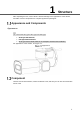
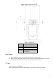
1 Structure After unpacking the box, check if there is obvious damage to the appearance of the camera, and make sure the components are complete against the packing list. Appearance and Components Appearance The camera has two types: Wi-Fi type and PoE type. Wi-Fi type: with antenna; PoE type: without antenna. Wi-Fi type camera will be taken as an example to introduce the installation. For appearance of the camera, see Figure 1-1.
Reset button and TF card Table 1-1 Component No. Name 1 Cover 2 Screw 3 TF card slot 4 Reset button Reset Button The reset button is used to restore the camera to the factory settings. After you have opened the camera rear cover, press and hold the reset button for over 10 seconds, and the camera will be restored to the factory default settings. TF Card The TF card is for data storage. Make the side with metal dots face downwards, and insert the card into the card slot.
When removing the TF card, if you push the card inside a little, and the card will be ejected automatically. Make sure that the TF card is removed when the camera is not communicating or transferring information; otherwise files will be corrupted and the TF card will be damaged. Cables 1.3.1 Cable Preparation Select video cables depending on the transmission distance. 1.3.2 Cable Requirement 75 ohm. Pure copper cored cables. 95% braided copper shielding.
Camera cables can be different depending on different models, and the actual cables shall prevail. Cables Table 1-4 Cable descriptions No. Description 1 FC connector 2 DC power input port 3 24V AC power input.
No. Description Grey: alarm input 3 Light green: alarm input 4 Purple: alarm input 5 White: alarm input 6 Yellow-black: alarm input 7 Do not carry the camera as displayed in Figure 1-4. Wrong way of carrying the camera Cable Connection Connect the multi-functional cable of the bracket to the multi-functional cable (including power cord, video cable, audio cable, RS-485 control cable, alarm cable, network cable, high-frequency signal cable, and optical fiber cable) of the camera.
The cable diameter of the RS-485 control cable can not be too large; otherwise the control performance can be influenced. For details of the RS-485 cable, see “Appendix 2 RS-485 Cable”. There are thermal contraction tube around the video output port. After the connection is finished, heat the two ends of the tube to make the video output port moistureproof and waterproof.
2 Install the Camera Check before Installation Make sure that the place where the camera is installed has enough space to hold the camera and its mounting accessories. Make sure that the bracket and wall where the camera is installed have the capacity to bear eight times the weight of the speed and its accessories. Make sure the wall is thick enough to allow bolts to be installed. If the camera is laser camera, the installation height should be above 6 meters.
Installation Procedure Depending on the installation base, the camera can be installed in two manners: installed on the wall and installed on the ceiling. 2.3.1 Installed on the Wall Stick stickers on the wall. Drill bolt holes in the wall according to holes on the sticker. Put expansion screws into the holes you drilled. Put expansion screws into the holes Connect the camera cables to external cables, put cables into the junction box, and then do waterproof operations.
Table 2-2 Components No. Name 1 ST4 Screw 2 Expansion Screw (Optional) Choose whether to install a junction box between the camera base and the wall or not. Install the junction box Table 2-3 Components No.
Install the Wi-Fi antenna to the camera cover. Install the Wi-Fi antenna Pull the Wi-Fi antenna up to complete the installation. Pull the Wi-Fi antenna up 2.3.2 Installed on the Ceiling Detach the mounting plate from the back of the camera.
Detach the mounting plate Drill bolt holes in the ceiling according to holes on the sticker. Place expansion screws into the ceiling. Place expansion screws into the ceiling Fix the mounting plate on the top of the camera.
Connect cables, do waterproof operations, and put cables into the junction box. Fix the camera on the ceiling. Fix the Camera on the ceiling Install the Wi-Fi antenna and pull it up to complete the installation.
Thunder-Proof and Surge Protection Install Lightning Protection Devices Indoors You shall use multiple copper cables whose cross-sectional area are not less than 25mm2 to connect the yellow-green ground cable/ground screws to the indoor equipotential earthing terminals. See Appendix figure 1-1. Appendix figure 1-1 Instal lightning protection device indoors Appendix table 1-1 Description of lightning protection device No.
RS-485 Cable General RS-485 industrial buses are half-duplex communication buses whose characteristic impedance is 120Ω. Its maximum load is 32 payloads (including drivers and receivers). RS-485 Transmission Distance When using 0.56 mm (24AWG) twisted pair, depending on different baud rates, the maximum theoretical transmission distances are listed. See Appendix table 2-1.
Appendix figure 2-1 The common manner of connecting devices To solve the problems, we recommend that you use RS-485 distributors. The RS-485 distributor can avoid the common manner of connection so as to improve transmission quality. See Appendix figure 2-2. Appendix figure 2-2 RS-485 distributor applied FAQ Problem Possible reason Solution Baud rate and IP address of the host and camera are not properly configured.
Problem Possible reason Solution control is not smooth. broken. new one. The distance between the host and camera is too long. Too many cameras connected in parallel. are Install terminal resistance. Install RS-485 distributors.
Relationship between Cable Diameter (12V DC) and Transmission Distance The recommended transmission distances are for reference only, and the actual conditions shall prevail. The chart below gives the maximum transmission distance of cables with certain diameters when the 12V DC power source voltage lose rate is bellow 10%. For cameras powered by direct current, the maximum voltage loss rate allowed is 10%. Cables mentioned in the table below are copper cables ( the resitivity of copper ρ = 0.
Wire Gauge Reference Sheet Metric bare wire diameter (mm) AWG SWG Bare wire cross section area (mm2) 0.050 43 47 0.00196 0.060 42 46 0.00283 0.070 41 45 0.00385 0.080 40 44 0.00503 0.090 39 43 0.00636 0.100 38 42 0.00785 0.110 37 41 0.00950 0.130 36 39 0.01327 0.140 35 / 0.01539 0.160 34 37 0.02011 0.180 33 / 0.02545 0.200 32 35 0.03142 0.230 31 / 0.04115 0.250 30 33 0.04909 0.290 29 31 0.06605 0.330 28 30 0.08553 0.350 27 29 0.09621 0.
Cybersecurity Recommendations Cybersecurity is more than just a buzzword: it’s something that pertains to every device that is connected to the internet. IP video surveillance is not immune to cyber risks, but taking basic steps toward protecting and strengthening networks and networked appliances will make them less susceptible to attacks. Below are some tips and recommendations on how to create a more secured security system. Mandatory actions to be taken for basic equipment network security: 1.
5. 6. 7. 8. 9. 10. 11. 12. 13. 14. Change Default HTTP and Other Service Ports We suggest you to change default HTTP and other service ports into any set of numbers between 1024~65535, reducing the risk of outsiders being able to guess which ports you are using. Enable HTTPS We suggest you to enable HTTPS, so that you visit Web service through a secure communication channel.
The network should be partitioned and isolated according to the actual network needs. If there are no communication requirements between two sub networks, it is suggested to use VLAN, network GAP and other technologies to partition the network, so as to achieve the network isolation effect. Establish the 802.1x access authentication system to reduce the risk of unauthorized access to private networks.