
Quick Start Guide
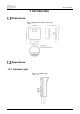
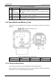
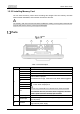
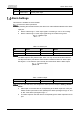
Table Of Contents

Quick Start Guide
4
No.
Name
Description
4
Power input
12V DC power input.
Alarm Settings
This function is available on select models.
Connect to alarm input device.
By following the instructions below, the device can collect different statuses of the alarm
input port.
Device collects logic “1” when input signal is connecting to +3V to +5V or idling.
Device collects logic “0” when input signal being connected to the ground.
Alarm input
Table 1-4 Alarm input
No.
Name
No.
Name
1
Alarm input
2
Ground wire
3
Network camera
4
Collecting
Connect to alarm output device.
The alarm output is relay switch output, which can only connect to NO alarm devices.
The N port and the C port with the same number constitute a switch for alarm output.
See Figure 1-6. The switch is open normally and closes when there is alarm output.
Alarm output
Table 1-5 Alarm output
No.
Name
No.
Name
1
Network camera
2
Alarm output
Log in to the web client, and configure the alarm input and output in Setting > Event >
Alarm.
Alarm input on the web client is corresponding to the alarm input end of I/O port.
Please set the input mode to “NO” (default) if the alarm input signal is logic “0” and
to “NC” if the alarm input signal is logic “1”.
The alarm output on the web client is corresponding to the alarm output end of I/O
port.