Quick Start Guide Visual Radar Quick Start Guide ZHEJIANG DAHUA VISION TECHNOLOGY CO., LTD. V1.0.
Quick Start Guide Foreword General This manual introduces the functions and operations of the visual radar (hereinafter referred to as "the Radar"). Model DH-PFR5QI-E60, DH-PFR5QI-E60-PV. Safety Instructions The following categorized signal words with defined meaning might appear in the manual. Signal Words CAUTION TIPS NOTE Meaning Indicates a potential risk which, if not avoided, could result in property damage, data loss, lower performance, or unpredictable result.
errors in print. If there is any doubt or dispute, we reserve the right of final explanation. Upgrade the reader software or try other mainstream reader software if the manual (in PDF format) cannot be opened. All trademarks, registered trademarks and the company names in the manual are the properties of their respective owners. Please visit our website, contact the supplier or customer service if there is any problem occurring when using the device.
Important Safeguards and Warnings The following contents are about the proper ways of using the Radar, preventing dangers and property damage when it is in use. Read the manual carefully before using the Radar, strictly abide by the manual and properly keep it for future reference. Environmental Requirements As for ground within the detection area, hard ground like concrete ground is optimal. As for ground covered by vegetation, the vegetation height should be below 20 cm.
diluent; otherwise the coating on the surface will be damaged and the performance of the Radar will be degraded. Use accessories suggested by the manufacturer, and install and maintain the Radar by professional personnel. Do not use two or more than two kinds of power supply modes to provide power for the Radar at the same time; otherwise, the device might be damaged.
Quick Start Guide Table of Contents Foreword .................................................................................................................................................... I Important Safeguards and Warnings .................................................................................................... III 1 Introduction............................................................................................................................................ 1 Dimensions ........
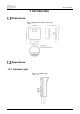
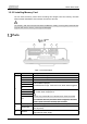
Quick Start Guide 1 Introduction Dimensions Radar dimensions (mm [inch]) Appearance 1.2.
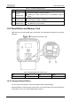
Quick Start Guide Table 1-1 Indicator light description No. 1 Name Description Status indicator light Solid green: Radar is running normally. Flashing red: Alarm events occur in the detection range of Radar. 2 Power indicator light Solid green: Radar is running normally. Flashing green: Radar is upgrading. 3 Network indicator light Solid yellow: Network is connected. Off: Network is not connected. 1.2.2 Reset Button and Memory Card Open the rear cover of the Radar with a screwdriver.
Quick Start Guide 1.2.2.2 Installing Memory Card You can insert a memory card to store recordings and images. Face the memory card with metal contacts downwards, and insert the card into the card slot. The memory card cannot be removed when the Radar is reading or writing data; otherwise files might be lost and the memory card might be damaged. Ports Ports Table 1-3 Port description No. Name Description A Connects to RS-485_A, controls external devices.
Quick Start Guide No. Name Description 4 Power input 12V DC power input. Alarm Settings This function is available on select models. Connect to alarm input device. By following the instructions below, the device can collect different statuses of the alarm input port. Device collects logic “1” when input signal is connecting to +3V to +5V or idling. Device collects logic “0” when input signal being connected to the ground. Alarm input Table 1-4 Alarm input No. Name No.
Quick Start Guide 2 Installation Installation Preparations 2.1.1 Environmental Requirements The installation site has enough space to install the Radar and its mounting components. The wall and pole for installation can sustain eight times the weight of the Radar and its mounting components. For wall mount, the wall shall be thick enough to install expansion bolts. No large areas of metals or glass objects are within the Radar detection range; otherwise mirrored alarm sites might occur.
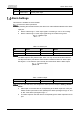
Quick Start Guide Horizontal direction In Figure 2-1, number 1 represents detection area and number 2 represents horizontal detection angle. Detection Range Due to the microwave feature, the detection distance of margins is shorter than the central detection distance. See Figure 2-1. Blind Zone for Short Distance The height of central point of the equivalent reflection interface of detected objects such as human and vehicle is above 1 m. Radar's maximum distance of blind zone is shown in Figure 2-2.
Quick Start Guide Max blind zone distance Table 2-1 Max blind zone distance No. Name No. Name 1 Installation height 2 Blind zone 3 Max. detection range — — Table 2-2 Max blind zone parameters (60 m radar) Installation height (h) Pitch Angle (α) Blind Zone Max Detection Range 2.0 m (6.56 ft) 0–3° 3.0 m (9.87 ft) 60.0 m (196.85 ft) 3.0 m (9.84 ft) 0–3° 5.0 m (16.40 ft) 60.0 m (196.85 ft) 4.0 m (13.12 ft) 0–3° 8.5 m (27.89 ft) 60.0 m (196.
Quick Start Guide Legal and regulatory information 1 Installation 2.4.1 Installing Methods Wall mount Pole mount 2.4.2 Installation Procedures The Radar panel is easy to be scratched, please install carefully. Remove the film after installation.
Quick Start Guide Radar panel This section takes wall mounting as an example.
Quick Start Guide Unscrew and remove the junction box Stick the positioning map and drill three screw holes The arrow direction in the positioning map always points to the left.
Quick Start Guide Install wall anchor and pull the cables out of the cable holes Thread the waterproof silicon plugs through the cables Install the junction box 11
Quick Start Guide Install the cables While installing the device, use safety rope to avoid dropping.
Quick Start Guide Adjust the detection angle and tighten the screws When adjusting the detection angle of the Radar, you can check the angle by enabling the device attitude on the web client. It is suggested that the angle of the device should be –3°, and the equipment should face the middle of the area to be monitored. See "4.2 Adjusting Radar Direction" for details. Verification after the Installation After the installation and all the wires are connected, verify if the Radar can work normally.
Quick Start Guide 3 Network Configuration Prerequisites Make sure that the IP addresses of your PC and the Radar are in the same network segment. The default IP address of the Radar is 192.168.1.108. You need to have relevant knowledge of radar product and its basic operations. Device Initialization The Radar needs to be initialized for the first-time use or after restoring to factory defaults. Open IE browser, enter the IP address of the Radar in the address bar, and then press Enter.
Quick Start Guide End-user license agreement Configure the time zone, and click Next. Time zone setting Set the password according to the prompt, and click Next.
Quick Start Guide Set admin password The email address is for password reset. We recommend entering the email address to guarantee normal use of the Radar. Select P2P in the P2P interface as needed, and click Next. P2P Select Auto-check for updates as needed, and then click Save to complete initialization.
Quick Start Guide Online upgrade Logging in to the Web Client You need to download and install the plug-in for the first time login. On the web interface, enter username and password, and then click Login. Login interface The default username is admin, and the password is the one that set during initialization. If you enter the wrong password for continuously 5 times, the account will be locked for 5 minutes. After the locked time ends, you can log in to the Radar again.
Quick Start Guide Install the plug-in After the plug-in is installed, the login interface is refreshed automatically. Enter username and password again, and then click Login. The live view interface is displayed. Live view Changing IP Address Configure IP address appropriately according to the actual network usage, and make sure that the Radar can access the network. Log in to the web interface of the Radar and select Setting > Network > TCP/IP.
Quick Start Guide TCP/IP 19
Quick Start Guide 4 Quick Operation Configuring Calibration To raise the detecting accuracy, we recommend configuring calibration of a moving person or object within the Radar detection range. 4.1.1 Auto Calibration To configure the auto calibration: Enable device attitude in Setting > Radar Settings > Device Attitude. Select Setting > Radar Settings > Linkage. In the calibration mode drop-down list, select Auto.
Quick Start Guide 4.1.2 Manual Calibration To configure the manual calibration: In the calibration mode drop-down list, select Manual. Click Start Calibration. Adjust the position of the bounding box through the directional buttons and speed on the right side of the live view, so that the position of the box is basically synchronized with the position of the moving person or car. Manual calibration Click Stop Calibration to save the settings.
Quick Start Guide Device Attitude Adjust the direction of the Radar. The recommended pitch angle is –3° and the roll angle is 0°. Click Save.
Quick Start Guide FAQ Problem Solution When the Radar is powered on, the power indicator light will No response after the Radar is powered on. glow. If not, check whether the power cord is firmly connected. Check whether the polarity of the power cord is correct, the supply current and voltage conform to the Radar label, and PoE (802.3at) power supply is normal. Power supply is normal but Make sure that radar's installation direction is correct. See "2.
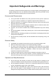
Quick Start Guide Cybersecurity Recommendations Cybersecurity is more than just a buzzword: it’s something that pertains to every device that is connected to the internet. IP video surveillance is not immune to cyber risks, but taking basic steps toward protecting and strengthening networks and networked appliances will make them less susceptible to attacks. Below are some tips and recommendations on how to create a more secured security system.
Quick Start Guide 5. 6. 7. 8. 9. 10. 11. 12. 13. Change Default HTTP and Other Service Ports We suggest you to change default HTTP and other service ports into any set of numbers between 1024~65535, reducing the risk of outsiders being able to guess which ports you are using. Enable HTTPS We suggest you to enable HTTPS, so that you visit Web service through a secure communication channel.
Quick Start Guide Establish the 802.1x access authentication system to reduce the risk of unauthorized access to private networks. Enable IP/MAC address filtering function to limit the range of hosts allowed to access the device.
27