
Users Manual Part 1


55
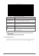
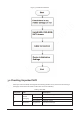
Figure 2-75 Alarm port
Table 2-41 Alarm port description
Icon
Function
1
–16
ALARM1
–ALARM16. The alarm becomes activated in the low level.
NO1 C1, NO2 C2, NO3
C3, NO4 C4
Four NO activation output groups. (On
-off button).
NO5 C5 NC5
One NO/NC activation output group. (On
-off button).
CTRL (CTRL 12 V)
Control power output. Disable power output when alarm is canceled.
Current is 500 mA.
P (+12 V)
Rated current output. Current is 500 mA.
GND.
A/B
485 communication port. They are used to control devices such as
PTZ. Please p
arallel connect 120 TΩ between A/B cables if there are
too many PTZ decoders.
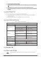
● Different models support different alarm input ports. Please see the specifications sheet for
detailed information.
● Slight difference might be found on the alarm port layout.
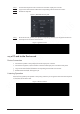
2.3.2 Alarm Input Port
Connect the positive end (+) of the alarm input device to the alarm input port (ALARM IN 1–16) of the
NVR. Connect the negative end (-) of the alarm input device to the ground end ( ) of the NVR.