
Users Manual Part 1

49
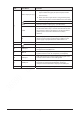
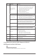
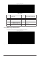
No.
Port Name
Function
Alarm output port
(NO1
-NO5, C1-C5,
NC5)
●
Five groups of alarm output ports (Group 1: NO1-C1,
Group 2: NO2-C2, Group 3: NO3-C3, Group 4: NO4-C4,
Group 5: NO5, C5, NC5). Output alarm signal to the
external alarm device. Make sure power supply is
available for the external alarm device.
●
NO: Normal open alarm output port.
●
C: Alarm output public end.
●
NC: Normal close alarm output port.
GND. Alarm input ground port.
RS
-485 port (A, B)
●
RS485_A port. Control cable A of the 485 device. It
connects external devices such as speed dome and PTZ.
●
RS485_B port. Control cable B of the 485 device. It
connects external devices such as speed dome and PTZ.
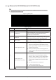
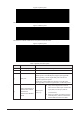
CTRL
Controllable 12 V power output. It
is to control the on-off
alarm relay output. It can be used to control the device alarm
output. At the same time, it can also be used as the power
input source of some devices such as alarm detector.
+12 V power output port. It can provide power to
some
peripheral devices such as camera and alarm device. Make
sure the power supply of peripheral device shall be below 1
A.
8
MIC IN
Bidirectional talk input port. It is to receive analog audio
signal from devices such as microphone, sound pickup.
MIC
OUT
Audio output port. It is to output analog audio signal to
devices such as sound box.
●
Bidirectional talk output.
●
Audio output on 1-window video monitor.
●
Audio output on 1-window video playback.
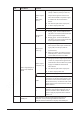
9
USB port
USB 3.0 port. Connect to devices such
as mouse, USB
storage device and USB burner.
10
Network port
10/100/1000 Mbps self
-adaptive Ethernet port. Connect to
the network cable.
11
Power input port
Input power of 100V
-240V and 50Hz-60Hz.
12
GND.
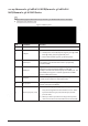
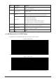
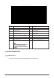
2.2.25 Advanced 1U 16PoE AI NVR /Advanced 1U 8PoE AI
NVR/General 1U 16PoE AI NVR Series
These figures are for reference only.
The Advanced 1U 16PoE AI NVR series rear panel is shown as below.