
Quick Start Guide
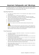


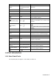

Table Of Contents
- Foreword
- Important Safeguards and Warnings
- 1 Introduction
- 2 Start and Shutdown
- 3 Quick Configuration
- 4 System Configurations
- 4.1 Preview
- 4.2 Playback
- 4.3 TV Wall
- 4.4 Platform
- 4.5 PTZ Control
- 4.6 Settings
- 4.7 Extension
- Appendix 1 Cybersecurity Recommendations

Introduction 4
Rear panel port Figure 1-3
Table 1-3 Rear panel port description
Number
Name
Description
1
Wi-Fi port
Connect Wi-Fi antenna.
2
Grounding stud
Grounding.
3
USB2.0
Connect mouse and USB.
4
RS–232
Connect serial port.
5
Alarm input/output port
For details, see Table 1-4.
6
Network port
Connect the network.
7
USB3.0
Connect mouse and USB.
8
Microphone
Connect microphone.
9
Earphone
Connect earphone.
10
HDMI1–HDMI4
Connect devices with HDMI port, such as display
screen.
11
Power port
Connect power cord to supply power.
12
Power button
Turn on and off the power supply.
For alarm input and output port, see Figure 1-4. For details, see Table 1-4.
Alarm input and output port Figure 1-4
Table 1-4 Alarm input and output port description
Name
Description
1–4
Alarm input port.
Reserved. The software does not support at present.
12V
12V DC 4A power.
G
Grounding.
A, B
Connect PTZ through RS–485.