
User's Manual


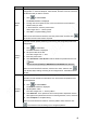


Table Of Contents
- Regulatory Information
- Cybersecurity Recommendations
- Foreword
- Important Safeguards and Warnings
- 1 Product Introduction
- 2 Dimension and Installation
- 3 Boot up the Device
- 4 Local Configurations
- 4.1 Initializing Device
- 4.2 Logging into the Device
- 4.3 Quick Configuration
- 4.4 Common Operations
- 4.5 Alarm Configuration
- 4.5.1 Alarm
- 4.5.2 Configuring Video Detection Settings
- 4.5.3 Configuring Alarm Events Settings
- 4.5.4 Abnormality
- 4.5.5 Configuring Alarm Output Settings
- 4.5.6 Searching Alarm Log
- 4.6 System config
- 4.7 System Update
- 4.8 System Maintenance
- 5 Web Operations
- 5.1 Initializing Device
- 5.2 Logging into the Device
- 5.3 Quick configuring
- 5.4 Common operations
- 5.5 System Settings
- 5.6 System Update
- 5.7 System Maintenance
- 6 Operating by DSS
- 7 FAQ
- Appendix 1 Mouse Operations
- Appendix 2 HDD Capacity Calculation
- Appendix 3 Technical parameters

43
Function
Description
Scan
After setting up scan, the camera automatically scans the configured left border
and right border
17. Click to select Border.
The Border interface is displayed.
18. Through the PTZ control panel, move the camera to the left border that you
want and click Set the left border; move the camera to the right border that
you want and click Set the right border. Configuration finished
Return to the PTZ function interface. Click to enable scan.
Pan
Click . The camera PTZ will continuously rotate in a horizontal way by 360
degrees.
AUX
Controls the screen wiper of external device through RS-485 command. To use
this function, make sure it is supported on the external device
Click to enable and disable light, wiper or defogging. Use the auxiliary
command to enable power-on setting or power-off reset PTZ.
PTZ
menu
Click to enable the PTZ menu. Operate and configure the camera through
the PTZ menu.
Flip
Click to flip display the video image.
Reset
Click to reset the PTZ.
4.4.1.4 Configuring Image settings
Right-click Image Color on the digital channel of the enabled video image.
The IPC Config interface is displayed. See Figure 4-23.