
User's Manual


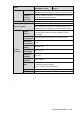
Table Of Contents
- Regulatory Information
- Cybersecurity Recommendations
- Foreword
- Important Safeguards and Warnings
- 1 Product Introduction
- 2 Dimension and Installation
- 3 Boot up the Device
- 4 Local Configurations
- 4.1 Initializing Device
- 4.2 Logging into the Device
- 4.3 Quick Configuration
- 4.4 Common Operations
- 4.5 Alarm Configuration
- 4.5.1 Alarm
- 4.5.2 Configuring Video Detection Settings
- 4.5.3 Configuring Alarm Events Settings
- 4.5.4 Abnormality
- 4.5.5 Configuring Alarm Output Settings
- 4.5.6 Searching Alarm Log
- 4.6 System config
- 4.7 System Update
- 4.8 System Maintenance
- 5 Web Operations
- 5.1 Initializing Device
- 5.2 Logging into the Device
- 5.3 Quick configuring
- 5.4 Common operations
- 5.5 System Settings
- 5.6 System Update
- 5.7 System Maintenance
- 6 Operating by DSS
- 7 FAQ
- Appendix 1 Mouse Operations
- Appendix 2 HDD Capacity Calculation
- Appendix 3 Technical parameters

Technical parameters 214
Model
MXVR4104-4 (4
identification routes)
MXVR4104-8 (8 identification
routes)
Allows for reviewing external alarms and video loss alarms
through the network
Allows for downloading, storing, and playing back recording
files
Supports building in 3G modules that work with Telecom,
Mobile, and Unicom.
Video loss
and alarm
Video loss
Able to link with external alarm output or pop up prompts
External
alarm
Able to link with recording, or link with external alarm output
or pop up prompts
Manual
alarm
control
Can enable or disable an alarm input channel
Able to simulate and generate alarm signals to be exported
to an alarm output channel
Alarm Input
10 routes of alarm input (you can select alarm types by
enabling/disabling Always Open or Always Close)
Alarm
Output
Four routes of controllable 12V alarm output
Interface
USB
interface
Two USB interfaces (one on the front panel, and one
extended out of the rear panel through cable)
Network
interface
RJ45 10M/100M self-adaptive Ethernet port (allows fixing
cables)
RS485
1
CAN
Two CAN interfaces that require the support of custom
programs
RS232
Four RS232 interfaces: One front DB9 interface, one used as
a common serial port (debugging), two for service connection
VGA
Supports (custom optional cable), workable with
purpose-made car-mounted touchscreen
Speed
One route of impulse speed input
Analog input
Two routes of analog input
Information
HDD
information
Display HDD usage and relevant information
Viewing Data
Rate
Information
Stream statistics and waveform display of each channel
Finding log
Displays system log and allows for finding log information by
time and type
System
status
information
Displays vehicle status, voltage, ACC status, system version,
and release date
User
Management
User
Management
Multi-level user management
Multiple management modes that cover the collective
management of local users, serial port users, and network
users, and allows for setting up user permissions