User Manual Revision V0.
Table of Contents Revision History ......................................................................................... 1 1. Introduction ............................................................................................ 1 1.1 General Description............................................................................................ 1 1.2 Features ............................................................................................................. 1 1.3 Applications .............
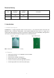
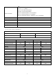
Revision History Date Document Product Revision Revision 0.1 V0.1 2019/07/15 Description Preliminary release 1. Introduction 1.1 General Description BL-M8822CU1 is a highly integrated module that was built in a 2*2 dual-band wireless LAN radio and Bluetooth radio. It combines a WLAN MAC, a 2T2R capable WLAN base band, and RF in a single chip. It supports IEEE 802.
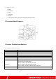
1.3 Applications MID IP Camera STB Smart TV E-book Other devices which need to be supported by wirelessnetwork 2. Functional Block Diagram Figure 3 BL-M8822CU1 3. Product Technical Specifications 3.1 General Specifications Item Description Product Name BL-M8822CU1 Main Chip RTL8822CU-CG Host Interface USB2.0 for WiFi and Bluetooth IEEE Standards IEEE 802.11a/b/g/n/ac Operating Frequencies 2.4~2.4835GHz, 5.180~5.835 GHz WiFi : 802.11b DSSS: CCK, DQPSK, DBPSK 802.
WiFi: 802.11b: 1, 2 ,5.5,11Mbps, 802.11a: 6,9,12,18,24,36,48,54Mbps, 802.11g:6,9,12,18,24,36,48,54Mbps, Wireless Data Rate 802.11n-2.4/5G HT20: MCS0~15, 6.5~144.4Mbps, 802.11n-2.4/5G HT40: MCS0~15, 13~300Mbps, 802.11ac-VHT20:MCS0~8 VHT40、80:MCS0~9 ,reach up to 867Mbps Rx Sensitivity -95dBm (Min) Antenna Type PCB Antenna Dimension(L*W*H) 27*17.8*3.0mm (LxWxH) Tolerance:+/-0.15mm Clock Source 40MHz Working Temperature -10℃ to +70℃ Storage Temperature -40℃ to +85℃ 3.
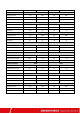
RX mode 62 802.11n HT40 73 62 MCS0 75 MCS7 Supply current Typ. Max. Typ. Max. Continuous TX mode 332 604 189 476 RX mode 60 74 61 75 802.11n HT40 MCS 8 MCS15 Supply current Typ. Max. Typ. Max. Continuous TX mode 242 404 143 410 RX mode 63 75 62 73 802.11a 6Mbps 54Mbps Supply current Typ. Max. Typ. Max. Continuous TX mode 459 712 283 762 RX mode 60 74 58 72 802.11n HT20(5G) MCS0 MCS7 Supply current Typ. Max. Typ. Max.
3.3 WiFi RF Specification WiFi-2.4G: 18.0±1.5dBm&<-15dB@11b 11Mbps 16.0±1.5dBm&<-28dB@11g 54Mbps 16.0±1.5dBm&<-28dB@11n-HT20/40-MCS7 TX Power & EVM WiFi-5G: 16.0±2dBm&<-28dB@11a 54Mbps 15.0±2dBm&<-28dB@11n-HT20/40-MCS7 14±2dBm&<-32dB@11ac-HT80-MCS9 WiFi-2.
4.
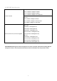
19 HSDP USB 2.0 differential line 20 HSDM USB 2.0 differential line 21 VBAT 3.3V Main Power Supply 22 RESET System reset signal active low 23 BT_WAKE_HOST BT wake up host 24 GPIO7 HOST wake up WLAN /SPI flash data line SIO3(NC) 25 HOST_WAKE_BT HOST wake up BT 26 EECS SPI flash chip select pin(NC) 27 EESK SPI flash clock pin(NC) 28 GPIO4 SPI flash data line SIO0(NC) 29 GND Ground connections 30 BT_ANT BT _ANT 31 GND Ground connections 5.
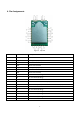
6. Mechanical Specifications Module dimension: Typical ( L*W *H): 27mm*17.8mm*3.0mm Tolerance : +/-0.
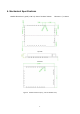
7. Antenna specification Antenna Type: Ant0: PCB Antenna Ant1: PCB Antenna Antenna Gain: Ant0: 2412MHz to 2462 MHz: 6.07 dBi 5150 MHz to 5250 MHz: 5.02 dBi 5250 MHz to 5350 MHz: 6.15 dBi 5470 MHz to 5725 MHz: 8.46 dBi 5725 MHz to 5850 MHz: 9.23 dBi Ant1: 2412MHz to 2462 MHz: 5.15 dBi 5150 MHz to 5250 MHz:6.45 dBi 5250 MHz to 5350 MHz: 6.48 dBi 5470 MHz to 5725 MHz: 7.26 dBi 5725 MHz to 5850 MHz: 5.38 dBi 8. Others 8.1 Package Information 土备注:小批量采用托盘包装 Figure 7 Package Information 8.
illustrated in Figures 15. The peak temperature is 245℃.
U.S. FCC Part 15 Regulatory Information This device complies with part 15 of the FCC Rules. Operation is subject to the following two conditions: (1) This device may not cause harmful interference, and (2) this device must accept any interference received, including interference that may cause undesired operation. Any Changes or modifications not expressly approved by the party responsible for compliance could void the user's authority to operate the equipment.
This device complies with FCC part 15C: 15.247 and 15.407. This device and its antenna(s) must not be co-located or operating in conjunction with any other antenna or transmitter. The module should be installed at a minimum distance of 20 cm away from a person nearby. The host product manufacturer should state this information to the host instruction manual. Trace antenna designs - not applicable.