24 GHz Radar Detector User’s Manual ZHEJIANG DAHUA VISION TECHNOLOGY CO., LTD. V1.0.0 ZHEJIANG DAHUA VISION TECHNOLOGY CO., LTD. V1.0.
User’s Manual Foreword General This manual introduces the functions and operations of the 24 GHz radar detector (hereinafter referred to as the "Radar"). Model DHI-ITARD-024SA-ST Safety Instructions The following categorized signal words with defined meaning might appear in the manual. Signal Words Meaning Indicates a high potential hazard which, if not avoided, will result in death or serious injury.
User’s Manual updates might cause some differences between the actual product and the manual. Please contact the customer service for the latest program and supplementary documentation. There still might be deviation in technical data, functions and operations description, or errors in print. If there is any doubt or dispute, please refer to our final explanation. Upgrade the reader software or try other mainstream reader software if the manual (in PDF format) cannot be opened.
User’s Manual Important Safeguards and Warnings This chapter introduces the contents covering proper handling of the Radar, hazard prevention, and prevention of property damage. Read these contents carefully before using the Radar, comply with them when using, and keep the manual well for future reference. Pay attention to personnel safety when installing the Radar at intersections or certain road sections. Non-professionals are forbidden to disassemble and install the Radar.
User’s Manual Maintenance Requirements WARNING Use accessories suggested by the manufacturer, and install and maintain the Radar by professionals. Do not provide two or more power supply modes; otherwise, the Radar might be damaged.
User’s Manual Table of Contents Foreword .................................................................................................................................................... I Important Safeguards and Warnings .................................................................................................... III 1 Product Introduction ............................................................................................................................. 1 1.1 Overview ................
User’s Manual 1 Product Introduction 1.1 Overview The 24 GHz radar detector is a narrow beam radar with planar antenna system. It is specifically designed to detect moving vehicles to meet modern traffic management challenges. The product uses modern microwave radar technology and high-speed digital signal processing technology for precise positioning and accurate speed measurement.
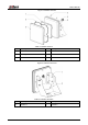
User’s Manual 2 Device Structure 2.1 Dimensions Figure 2-1 Front view (mm (inch)) Figure 2-2 Side view (mm (inch)) 2.2 Structure The device structure relates to the Radar and the bracket. See Figure 2-3 and Figure 2-4.
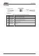
User’s Manual Figure 2-3 Radar structure Table 2-1 Radar structure No. Description No. Description 1 Antenna 4 Set screw 2 Sealing washer 5 PG connector 3 Front cover 6 Rear cover Figure 2-4 Bracket structure Table 2-2 Bracket structure No. Description No.
User’s Manual 2.3 Cable Figure 2-5 Cable Table 2-3 Description of 6-pin 2.5mm pitch connector Pin Name Description 1 12V DC (black) GND pin for radar power supply. 2 12V DC (red) Pin for 12V radar power supply. 3 TXD (green) TX pin for radar RS-232 communication, baud rate 9600, connects to R1, R2 and R3 ports of camera. 4 RXD (yellow) RX pin for radar RS-232 communication, connects to T1, T2 and T3 ports of camera.
User’s Manual 3 Installation 3.1 Fixing the Radar to Brackets The brackets help fix the Radar and adjust the angle of the Radar. Step 1 Fix bracket 1 to the Radar with four M6 × 8 hex socket cap screws. Figure 3-1 Fix bracket 1 Step 2 Fix bracket 2 to bracket 1 with four M6 × 20 flat spring screws.
User’s Manual 3.2 Installing the Radar over Lane You can use tools to improve your installation, such as digital protractor, portable inclinometer, and more. Step 1 Install the Radar on traffic pole right above the lane. Figure 3-3 Install the Radar on traffic pole Step 2 Adjust the Radar position to make it aim at the middle position of the detected lane.
User’s Manual Figure 3-5 Radar installation example 7
User’s Manual 4 Radar Configuration on Camera Web Install the Radar (see "3 Installation"), connect the Radar to camera (see "2.3 Cable"), and then set the radar parameters on the web interface of camera, so the Radar can work with the camera to detect and capture vehicles. Step 1 Open the browser, enter the IP address of the camera in the address bar, and then press the Enter key. Step 2 Enter the username and password, and click Login to log in to the web interface of the camera.
User’s Manual Parameter Description The way of sending information captured by the Radar. You can select Single, Continuous or Manual. Work Mode Currently, camera supports only Single. Special program is required if you want to send the information in continuous or manual way. Interval The interval that the Radar detects and recognizes an object. Detect Mode The detection direction of the Radar, which includes Approaching, Departing, and Both.
User’s Manual 5 FAQ The Radar is a high-technology product that requires professional operations. Read the user's manual carefully before using the Radar, or contact professionals or technical support if you have any doubts. This section provides guidance on solving some typical problems related to the Radar.
User’s Manual Appendix 1 Cybersecurity Recommendations Cybersecurity is more than just a buzzword: it’s something that pertains to every device that is connected to the internet. IP video surveillance is not immune to cyber risks, but taking basic steps toward protecting and strengthening networks and networked appliances will make them less susceptible to attacks. Below are some tips and recommendations on how to create a more secured security system.
User’s Manual 5. 6. 7. 8. 9. 10. 11. 12. 13. 14. Change Default HTTP and Other Service Ports We suggest you to change default HTTP and other service ports into any set of numbers between 1024~65535, reducing the risk of outsiders being able to guess which ports you are using. Enable HTTPS We suggest you to enable HTTPS, so that you visit Web service through a secure communication channel.
User’s Manual The network should be partitioned and isolated according to the actual network needs. If there are no communication requirements between two sub networks, it is suggested to use VLAN, network GAP and other technologies to partition the network, so as to achieve the network isolation effect. Establish the 802.1x access authentication system to reduce the risk of unauthorized access to private networks.
User’s Manual
Federal Communications Commission (FCC) Interference Statement This device complies with Part 15 of the FCC Rules. Operation is subject to the following two conditions: 1. This device may not cause harmful interference. 2. This device must accept any interference received, including interference that may cause undesired operation. Note: This equipment has been tested and found to comply with the limits for a Class A digital device, pursuant to Part 15 of the FCC Rules.