IP Camera User’s Manual Version 1.0.0 Zhejiang Dahua Technology CO.
Welcome Thank you for purchasing our network camera! This user’s manual is designed to be a reference tool for your system.
Important Safeguards and Warnings 1. .Electrical safety All installation and operation here should conform to your local electrical safety codes. The power shall conform to the requirement in the SELV (Safety Extra Low Voltage) and the Limited power source is rated 12V DC or 24V AC in the IEC60950-1.
Do not touch the CCD (CMOS) optic component. You can use the blower to clean the dust on the lens surface. Always use the dry soft cloth to clean the device. If there is too much dust, please use the water to dilute the mild detergent first and then use it to clean the device. Finally use the dry cloth to clean the device. Please put the dustproof cap to protect the CCD (CMOS) component when you do not use the camera.
Table of Contents 1 General Introduction ..................................................................................................................1 1.1 Overview ........................................................................................................................1 1.2 Features.........................................................................................................................1 1.3 Specifications ............................................................
1 General Introduction Introduction 1.1 Overview This series network camera integrates the traditional camera and network video technology. It adopts video data collection, transmission together. It can connect to the network directly without any auxiliary device. This series product uses standard H.264 video compression technology, G.711a audio compression technology and etc, which maximally guarantees the video quality. It supports PIR function to detect human body movement.
! Assistant Function Warning Do not connect these two power supplying sources to the device at the same time; it may result in device damage! Log function. Support system resource information and running status real-time display. Backlight compensation: screen auto split to realize backlight compensation to adjust the bright. Support video watermark function to avoid vicious video modification. Support picture parameter setup such as electronic shutter and gain setup.
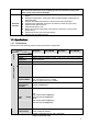
Video Flip Snapshot Privacy Mask Video Setup Video Information Channel title, time title, motion detect, camera masking. Lens Interface 3.6mm. Fixed focus. Angle of view: 70°(H *51.5°(V) M12. Lens is the default accessories Audio Bit Stream One-way Dual-way Audio Input/Output Built-in microphone Built-in microphone and speaker Lens Audio Audio Bit Rate Audio Compression Standard ) 8/16kbps 16bit G.711A/G.
General Parameter Power Power Consumption Working Temperature Working Humidify Dimensions(mm) Weight Installation DC 12V 3.4W MAX -30 ℃~+60℃ ≤95% 5.4W MAX -30 ℃~+55℃ 3.4W MAX -30 ℃~+60℃ 5.4W MAX -30 ℃~+55℃ 66.6*99.5*131.2 200g Excluding box Installation with the bracket.
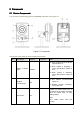
2 Framework 2.1 Device Components You can refer to the following figure for component information. See Figure 2-1. Figure 2-1 Component Please refer to the following sheet for detailed information. SN Port Name Indicator Connector Note When system boots up–Green light becomes on. 1 Power indicator light POWER / When system is upgrading – Green light flashes. Interval is 0.5s. When system is alarming– Green light flashes. Interval is 0.2s.
SN Port Name Indicator Connector Note 4 IR light / / For lighting at night 5 Speaker / / Output audio signal. (This function is optional. For some series product only.) 6 Microphone / / Directly receive audio signal. 7 Micro SD card Micro SD Micro SD card slot SD card storage. (This function is optional. For some series product only.). 8 Network port LAN Ethernet port Connect to standard Ethernet cable. 9 Power port DC12V / Input DC 12V power.
2.3 Bidirectional talk 2.3.1 Device-end to PC-end Device Connection Please connect the earphone to the audio output port in the PC. Login the Web and then click the Audio button to enable the bidirectional talk function. You can see the button becomes yellow after you enabled the audio talk function. Click Audio button again to stop the bidirectional talk function.
3 Device Installation This series camera support two installation modes: wall mount and pendant mount. See Figure 3-1 and Figure 3-2. Important Please make sure the installation surface can min support the 3X weight of the camera and the bracket. Step 1 Paste the installation map on the installation surface such as wall, ceiling or the wood. Step 2 Dig holes in the installation surface according to the installation map.
Fix the device with screw in the accessories bag. Step 5 Connect the cable and then boot up the device. Step 6 Loosen the adjust knob for a little bit, adjust the camera to proper surveillance position according to your actual requirements. Step 7 Secure the knob of the bracket to fix the camera.
4 Quick Configuration Tool 4.1 Overview Quick configuration tool can search current IP address, modify IP address. At the same time, you can use it to upgrade the device. Please note the tool only applies to the IP addresses in the same segment. 4.2 Operation Double click the “ConfigTools.exe” icon, you can see an interface is shown as in Figure 4-1. In the device list interface, you can view device IP address, port number, subnet mask, default gateway, MAC address and etc.
If you want to modify the device IP address without logging in the device web interface, you can go to the configuration tool main interface to set. In the configuration tool search interface (Figure 4-1), please select a device IP address and then double click it to open the login interface. Or you can select an IP address and then click the Login button to go to the login interface. See Figure 4-3. In Figure 4-3, you can view device IP address, user name, password and port.
5 Web Operation This series network camera products support the Web access and management via PC. Web includes several modules: Monitor channel preview, system configuration, alarm and etc. 5.1 Network Connection Please follow the steps listed below for network connection. Make sure the network camera has connected to the network properly. Please set the IP address, subnet mask and gateway of the PC and the network camera respectively. Network camera default IP address is 192.168.1.108.
Figure 5- 2 Web login After you successfully logged in, please install WEB plug-in unit. Please refer to the Web Operation Manual included in the resource CD for detailed operation instruction. See Figure 5- 3.
6 FAQ Bug I can not boot up the device. Please click RESET button for at least five seconds to restore factory default setup. SD card hot swap Before draw out SD card, please stop record or snapshot first and then wait for at least 15 seconds to remove the SD card. All the operations before is to maintain data integrity. Otherwise you can lose all the data in the SD card! SD card times Do not set the SD card as the storage media to storage the schedule record file. It may damage the SD card duration.
Bug Power adapter ℃ ℃. The general power adapter can work ranging from 0 to 40 The device may result in unstable power supply when the temperature exceeds the working temperature. Please replace an industry-level power adapter if you are using in the harsh environments.
Appendix Toxic or Hazardous Materials or Elements Component Name Toxic or Hazardous Materials or Elements Pb Hg Cd Cr VI PBB PBDE Circuit Board Component ○ ○ ○ ○ ○ ○ Device Case ○ ○ ○ ○ ○ ○ Wire and Cable ○ ○ ○ ○ ○ ○ ○ ○ ○ ○ ○ ○ ○ ○ ○ ○ ○ ○ Packing Components Accessories O: Indicates that the concentration of the hazardous substance in all homogeneous materials in the parts is below the relevant threshold of the SJ/T11363-2006 standard.
European notice Products with the CE marking comply with Radio & Telecommunication Terminal Equipment Directive (R&TTE) (1999/5/EC), the Electromagnetic Compatibility Directive (2004/108/EC) and the Low Voltage Directive (2006/95/EC) - issued by the Commission of the European Community.
FCC Compliance Statement 1. This device complies with Part 15 of the FCC Rules. Operation is subject to the following two conditions: (1) this device may not cause harmful interference, and (2) this device must accept any interference received, including interference that may cause undesired operation. 2.