HD Cube Network Camera Quick Start Guide Version 1.0.
Welcome Thank you for purchasing our network camera! This quick start guide is designed to be a reference tool for your system. Please keep this start guide well for future reference. Please open the accessory bag to check the items one by one in accordance with the list below. Contact your local retailer ASAP if something is missing or damaged in the bag. Before your operation please read the following instructions carefully.
Thunder-proof device is recommended to be adopted to better prevent thunder. The grounding studs of the product are recommended to be grounded to further enhance the reliability of the camera. 6. Daily Maintenance Please shut down the device and then unplug the power cable before you begin daily maintenance work. Do not touch the CCD (CMOS) optic component. You can use the blower to clean the dust on the lens surface. Always use the dry soft cloth to clean the device.
Table of Contents 1 Structure ......................................................................................................................................1 1.1 Device Components.....................................................................................................1 1.2 Dimensions....................................................................................................................2 1.3 Bidirectional talk .............................................................
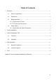
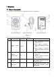
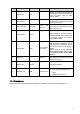
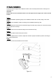
1 Structure 1.1 Device Components You can refer to the following figure for component information. See Figure 1-1. Figure 1-1 Please refer to the following sheet for detailed information. SN Port Name Indicator Connector Note z When system boots up–Green light becomes on. 1 Power light indicator POWER / z When system is upgrading – Green light flashes. Interval is 0.5s. z When system is alarming– Green light flashes. Interval is 0.2s. z Wire network connection-Red light is on.
SN Port Name Indicator Connector Note Passive IR motion detect port. It can detect the IR object movement (such as human body or other heating object). 5 PIR sensor PIR / 6 Microphone / / 7 Micro SD card Micro SD Micro SD card slot Directly receive audio signal. (This function is optional. For some series product only.). SD card storage. (This function is optional. For some series product only.). Restore factory default setup.
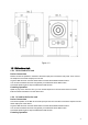
Figure 1-2 1.3 Bidirectional talk 1.3.1 Device-end to PC-end Device Connection Please connect the speaker or the MIC to the audio input port in the device rear panel. Then connect the earphone to the audio output port in the PC. Login the Web and then click the Audio button to enable the bidirectional talk function. You can see the button becomes orange after you enabled the audio talk function. Click Audio button again to stop the bidirectional talk function.
Speak or play music at the PC-end, you can use the built-in speaker of the device-end to listen. Note Please go to the Master Volume interface of the PC to set first if you want to use the dual-way bidirectional talk. Please select Front Mic mode in the record control interface. (You can select microphone enhanced in Advanced interface if the audio is too low.) 1.4 Alarm Setup The alarm setup interface is shown as below. See Figure 1-3. Figure 1-3 1.4.
Figure 1-5 5
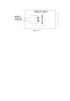
2 Device Installation This series camera support two installation modes: wall mount and pendant mount. See Figure 2-1 and Figure 2-2. Important Please make sure the installation surface can min support the 3X weight of the camera and the bracket. Step 1 Paste the installation positioning map on the installation surface such as wall, ceiling or the wood. Step 2 Dig holes in the installation surface according to the installation positioning map.
Figure 2-2 7
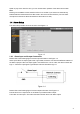
3 Quick Configuration Tool 3.1 Overview Quick configuration tool can search current IP address, modify IP address. At the same time, you can use it to upgrade the device. Please note the tool only applies to the IP addresses in the same segment. 3.2 Operation Double click the “ConfigTools.exe”icon, you can see an interface is shown as in Figure 3-1. In the device list interface, you can view device IP address, port number, subnet mask, default gateway, MAC address and etc.
Figure 3-2 Select the “Open Device Web” item; you can go to the corresponding web login interface. See Figure 3-3. Figure 3-3 If you want to modify the device IP address without logging in the device web interface, you can go to the configuration tool main interface to set. In the configuration tool search interface (Figure 3-1), please select a device IP address and then double click it to open the login interface.
Figure 3-4 After you logged in, the configuration tool main interface is shown as below. See Figure 3-5. Figure 3-5 For detailed information and operation instruction of the quick configuration tool, please refer to the Quick Configuration Tool User’s Manual included in the resources CD.
4 Web Operation These series network camera products support the Web access and management via PC. Web includes several modules: Monitor channel preview, system configuration, alarm and etc. . 4.1 Network Connection Please follow the steps listed below for network connection. z Make sure the network camera has connected to the network properly. z Please set the IP address, subnet mask and gateway of the PC and the network camera respectively. Network camera default IP address is 192.168.1.108.
Figure 4-2 If it is your first time to login in, system pops up warning information to ask you whether install control webrec.cab or not after you logged in for one minute. Please click OK button, system can automatically install the control. When system is upgrading, it can overwrite the previous Web too. If you can’t download the ActiveX file, please check whether you have installed the plug-in to disable the control download. Or you can lower the IE security level. See Figure 4-3.
Figure 4-4 Please refer to the Web Operation Manual included in the resource CD for detailed operation instruction.
5 FAQ Bug I can not boot up the device. Please click RESET button for at least five seconds to restore factory default setup. SD card hot swap Before draw out SD card, please stop record or snapshot first and then wait for at least 15 seconds to remove the SD card. All the operations before is to maintain data integrity. Otherwise you can lose all the data in the SD card! SD card times Do not set the SD card as the storage media to storage the schedule record file. It may damage the SD card duration.
Bug Power adapter z The general power adapter can work ranging from 0℃ to 40 ℃. The device may result in unstable power supply when the temperature exceeds the working temperature. z Please replace an industry-level power adapter if you are using in the harsh environments.
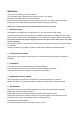
Appendix Toxic or Hazardous Materials or Elements Component Name Toxic or Hazardous Materials or Elements Pb Hg Cd Cr VI PBB PBDE Circuit Board Component ○ ○ ○ ○ ○ ○ Device Case ○ ○ ○ ○ ○ ○ Wire and Cable ○ ○ ○ ○ ○ ○ ○ ○ ○ ○ ○ ○ ○ ○ ○ ○ ○ ○ Packing Components Accessories O: Indicates that the concentration of the hazardous substance in all homogeneous materials in the parts is below the relevant threshold of the SJ/T11363-2006 standard.