DH-HWS800A Speed Measuring System User’s Manual Version 1.2.
Welcome Thank you for purchasing our product! This user’s manual is designed to be a reference tool for your system.
Important Safeguards and Warnings 1᧪ ᧪Electrical safety All installation and operation here should conform to your local electrical safety codes. We assume no liability or responsibility for all the fires or electrical shock caused by improper handling or installation. We are not liable for any problems caused by unauthorized modification or attempted repair. 2᧪ ᧪Installation This series product shall be installed one or three meters away from the lane.
6. Accessories Please open the accessory bag to check the items one by one in accordance with the list below. Contact your local retailer ASAP if something is missing or damaged in the bag.
Table of Contents 1 General Introduction .................................................................................................................. 1 1.1 Overview ........................................................................................................................ 1 1.2 Functions ....................................................................................................................... 1 1.3 Features ..............................................................
1 General Introduction 1.1 Overview The DH-HWS800A IR distance measuring system is a full embedded system featuring vehicle speed measurement, image snapshot, video monitor, automatically number plate recognition (ANPR) and etc. This series product perfectly meets the requirement of the traffic business of the public security and generally integrates the advantages of the domestic and overseas products. The built-in design is stable and of strong function.
can perform different levels of operation. Right verification is required. Multiple human and machine alternating ports The system provides fulltouch human and PC alternating interface. It is useful for your operation. Auto maintenance function Support auto maintenance function and customized maintenance period. System can restore previous working status after the reset operation. Vehicle classification Via radar classify vehicles into different types.
z Narrow beam radar speed measurement to enhance the accuracy, effectively hide from the electronic dog (anti-speed radar detector) Dahua self-developed high performance narrow wave radar can meet the international speed measurement accuracy. The narrow beam radar is rarely detected by the electric dog. It can effectively monitor the approaching and departing vehicles. z Industry-level component and high reliable socket connector The hardware circuit design adopts the industry-level components.
Host Spec Power output port: One 12V DC output port. Flashlight synchronization port: There is one port, optical signal output, support flashlight and IR light compensation. LED flashlight synchronization port: There is on port. Frequency and interval are adjustable.
z z z z z Specification of engineering of security and protection system(GB50348—2004) Specification of lightning-surge protection for security and protection system(GA/T 670-2006) Rules of engineering acceptance of TV monitoring system for traffic(GA/T 514-2004) Vehicle speeding auto-monitor system (JJG527-2007) Vehicle radar measurement device (JJG528-2004) z Vehicle speed measurement device (GB/T21255-2007) Technology specifications of image forensics for road traffic offences(GA/T832-2009) Chinese
2 Structure 2.1 System Structure HWS800A IR distance measuring system includes power, embedded interactive snapshot host, radar, LCD screen and touch screen. The host is core of the system and it is mainly responsible for snapshot, flashlight sync, camera control, radar speed measuring and receiving this value, image storage, network transmission, USB downloading and GUI display. 2.2 Appearance This series product appearance is shown as below. See Figure 2-1 and Figure 2-2.
Figure 2-2 2.3 Panel and Ports 2.3.1 Right Panel Please refer to the following figure for right panel information. See Figure 2-3.
Figure 2-3 Please refer to the following sheet for detailed information. No.
No. Line Color 2 3 - Description Blue TXD Yellow GND Power switch DC19V power input port 2.3.2 Front Panel The front panel is shown as in Figure 2-4.
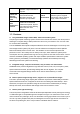
Please refer to the following sheet for detailed information. SN Icon Description Color Function Flashing: System is working properly. System running On: System has abnormity. Green 4 indication light Off: system has stopped working. Flashing: Lithium battery is Lithium battery recharging now,. recharge indication Blue 5 Off: The recharge is completed light or there is no battery available. 6 Power light Red On: System is on. Off: System is off. 2.3.
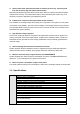
Please refer to the following sheet for detailed information. SN Port Name 7 SD card slot 8 Lithium battery Network, USB port, RS232 port, DC 12V power output 9 and etc.
3 Operation Important z Before your operation, please make sure all cable connections are right and the Lithium battery has inserted in the slot. z You need to click the Save button in the interface to save your current setup! 3.1 Boot up and Shut down 3.1.1 Boot up Push the power button in the side panel, you can see the red power indication light becomes on. The system is booting up now. 3.1.
If it is your first time to use the system, please select the user name from the dropdown list and then input the corresponding password in the soft keyboard. You can create your own account to login for the next time. See Figure 3-2. Figure 3-2 3.2.2 Main Interface The system main interface is shown as below. See Figure 3-3. It includes nine items: Traffic Flow, Monitor, Log, Backup, Snapshot, Query, User, Config and Information.
Figure 3-3 3.2.3 Snapshot Please highlight the “Snapshot” item and then click; you can see the following interface. Here you can see the vehicle snapshot image and view saved image information. See Figure 3-4. In the main pane, you can see the snapshot image. On the right pane, you can view the corresponding information. At the bottom of the interface, you can view four function buttons (from left to the right): previous image, manual snap, next image and return button. z Date: The image snapshot date.
Figure 3-4 3.2.4 Monitor The preview interface is shown as below. Here you can view vehicle real-time driving status. When you are debugging the system, you can go to the following figure to view the camera effect. See Figure 3-5. z Bright: Please click “-” and “+” button to adjust the brightness. The value ranges from 0 to 100. The default value is 50. z Contrast: Please click “-” and “+” button to adjust the contrast. The value ranges from 0 to 100. The default value is 50.
3.2.5 Config 3.2.5.1 Radar Setting The radar setting interface is shown as in Figure 3-6. z Low limit: Set to enable/disable low speed measuring and snapshot. You can set low limit after enabled. z Low value: Set value of low limit. When vehicle in area is slower than this value, snapshot is on. z Large or small: There are two options: disable/enable. There are two trigger speeds for the large and small vehicle respectively if you check the enable button here. The interface is shown as in Figure 3-7.
Figure 3-7 Note: Installation distance: Set first lane distance from location where the device locates. This shall be based on actual distance. Recommend 150cm. Lane width: Set lane width. Based on actual lanes, and do not fill in extra lanes. For example, is lane quantity is e, then leave 4th, 5th and 6th lanes empty. Default is 0 cm. 3.2.5.2 Camera Setting The camera setting interface is shown as below. See Figure 3-8. z Exposure mode: There are two options: fixed and auto.
Figure 3-8 Figure 3-9 3.2.5.3 OSD The OSD setting interface is shown as in Figure 3-10 and Figure 3-11. z Address: Please input the offence address via the Web or the local keyboard. z Lane SN: Please input the lane serial number here. z Direction: Please select the road direction from the dropdown list. It includes five options: No direction/from the north to the south/from the south to the north/from the east to the west/from the west to the east. z Edit: It includes two operations.
z z z Edit address: Pleas select one item from the dropdown list and then use the keyboard to edit. Please click the “Modify” button to complete the setup.. Import: This series product supports the import operation from the USB storage media. Please insert the USB device and then click the “Import” button to update the address list. Font color: Set OSD font color: red or white. OSD options: System supports the OSD function.
3.2.5.4 Network Setting The network setting interface is shown as in Figure 3-12. z Host IP: Here you can set host IP address. z Subnet mask: Here you can set host subnet mask. z Gateway: Here you can set host gateway. z DNS server1: Here you can set host DNS preferred address. z DNS server2: Here you can set host DNS alternate address. Figure 3-12 3.2.5.5 Server Setting The server setting interface is shown as in Figure 3-13.
Figure 3-13 3.2.5.6 Time Setting The time setting interface is shown as in Figure 3-14. z Time enable: You can check the box here to enable or disable the function. z Server IP: Please input NTP server IP address here. z Port No.: Please input NTP server port number here. The default setup is 37. z Sync period: It is the NTP auto synchronization period. The unit is minute and the default setup is 7 minutes. z Time zone: Please time zone from the dropdown list.
3.2.5.7 FTP Setting FTP setting interface is shown as in Figure 3-15. z FTP enable: You can check the box here to enable or disable the function. z FTP Server IP: Here you can input FTP server IP address. z Name: Please input the user name to login the FTP server. z Password: Please input the corresponding password here to login the FTP server. z Port No.: Please input the server port number. The default setup is 21. z Storage path: It is the image storage path saved in the FTP. Figure 3-15 3.2.5.
Figure 3-16 3.2.5.9 Intelligent The intelligent interface is shown as in Figure 3-17. z Plate recognition: You can check the box here to enable or disable the plate recognition function. System automatically recognizes the plate number and plate color after snapshot if you enable this function here. z Short name: It is the short name of your local place. z Plate recognition area: There are 12 zones for one 8 megapixel image.
Query: Display search result. White/Black list enable: Enable this function. Import trusted/black list: Support USB import of these lists. Export trusted/black list: Support USB export of these lists. Add trusted/black list: Enter plate no., vehicle owner name and select vehicle type to add. Note: White/black list has strict format, and you can refer to format of previous list. Figure 3-18 Figure 3-19 3.2.
3.2.6.1 Search by time The interface is shown as in Figure 3-20. There are four time periods: last day/last three days/last week/all. It also supports customize setup. Please click the “Custom” button to set. Figure 3-20 3.2.6.2 Search by speed range The interface is shown as in Figure 3-21. There are three items: overspeed <50%, overspeed >50 %( including 50%) and all. It also supports customize setup. Please click the “Custom” button to set.
Figure 3-21 After completed the search, you can see the following interface. See Figure 3-22. Figure 3-22 3.2.6.3 Search by Blacklist The interface is shown as in Figure 3-23. There are four time periods: last day/last three days/last week/all. It also supports customize setup. Or you can click the “Custom” button to customize.
Figure 3-23 You can see the image SN, snapshot time, speed, and vehicle plate and vehicle type. System displays the 8 records in one screen by default. You can use the previous/next button to view more images. After you select one image, the two snapshot images will be displayed in the thumbnail pane from the left to the right at the top pane. Here you can check the one or more images to delete or export. You can check the box before the “No” item to select all 8 images. See Figure 3-24.
3.2.7 Image Backup The image backup includes three modes: Backup by time (Figure 3-25)/backup by speed (Figure 3-26)/backup by blacklist (Figure 3-27). Backup by time and backup by speed are USB backup. During the backup process, you can see the corresponding process bar for your reference. System pops up the dialogue box when the backup completed.
Figure 3-27 3.2.8 System Information 3.2.8.1 Version Information The device status interface is shown as below. See Figure 3-28. z Software version: Here you can view the software main version including the compile date. z Hardware version: Here you can view the hardware main version. z GUI version: Here you can view the GUI module version. z Web version: Here you can view the Web module version. z Radar version: Here you can view radar version. Disconnected radar or abnormal radar will show as offline.
Figure 3-28 3.2.8.2 Device Information The device information interface is shown as below. See Figure 3-29. z Device type: The default type is HWS800A. z Device SN: It is the device serial number when it shipped out of the factory. Please note it is read-only. z Radar SN: It is the corresponding radar serial number. It can input in the system setup interface. You can refer to the metal plate at the side panel of the speed measuring system for the device SN and the radar SN information. Figure 3-29 3.2.
Here you can view network connection information including the user name, IP port and user type. The user type includes: WEB, network upgrade tool and platform software. Figure 3-30 3.2.8.4 Peripheral device information Click “Peripheral device information” button, you can see an interface is shown as in Figure 3-31. z Radar: It is the radar working status of current speed measuring system. It displays as OK when the radar works properly.
z z z z z Capacity (M):It is the capacity of the system special storage media. Usage(%): The usage percentage of current special storage media. It is shown as XX.XX%. Picture number: Here you can view system saved picture amount. Format: Format SD card. Unmount: uninstall SD card or USB. Figure 3-32 3.2.8.6 System Information The system information interface is shown as in Figure 3-33. z CPU usage: Here you can view current CPU usage status. It is shown as XX.XX%.
Figure 3-33 3.2.9 Traffic Flow The traffic flow statistics has two modes: by time (unit:: second) and by speed range. See Figure 3-34 and Figure 3-35. You can refer to the Image search interface for detailed information.
Figure 3-35 The traffic flow statistics result is shown as in Figure 3-36. It displays in column diagram. System supports export via the USB device. You can insert the flash disk to the USB port and then click the “Export” button to export current statistics results in txt file. Figure 3-36 3.2.10 Log System supports two log search modes: search by time period (Figure 3-37) and search by user name (Figure 3-38). In Figure 3-38, you can select the user name from the dropdown list.
Figure 3-37 Figure 3-38 The log search results interface is shown as in Figure 3-39. The searched results displayed in a sheet. There are total four columns: SN, time, details, and user name. There are 16 items in one screen. You can use the “Previous” and “Next” button to view more logs. Important Clear function here is to delete all logs in the system.
Figure 3-39 3.2.11 User Management The user management interface is shown as in Figure 3-40. It includes the following information: z z z z Group: It is the user group name the user belongs to. There are two levels: admin/user. User status: It includes two types: online/offline. It is shown as online after the user logged in the system. Otherwise it is shown as offline. Note: Here is some note information when you are adding current user.
In Figure 3-40, select one user and then click “Modify” button you can go to the following interface. See Figure 3-41. Here you can change password, modify property of the group, modify note information and modify rights setup. Figure 3-41 In Figure 3-40, select one user and then click “Add” button you can go to the following interface. See Figure 3-42. Here you can add new user, select the group for newly added user, add note information and select the corresponding rights.
4 Applications Here are some actual snapshot images for your reference. For privacy reasons, we hide some numbers in the plate. 4.1 Snapshot in the Daytime The approaching snapshot image in the daytime is shown as in Figure 4-1 and Figure 4-2..
Figure 4-2 4.2 Snapshot at Night The approaching snapshot image at night is shown as in Figure 2-3/Figure 2-4/Figure 2-5/ Figure 2-6.
Figure 2-4 Figure 2-5 40
Figure 2-6 41
5 Installation 5.1 Device Installation Take the device out of the box. Insert the Lithium battery. Put the device on the tripod and adjust to the proper height. Push the power button to boot up the device. 5.2 Camera Debug Go to the Road Monitor interface. Adjust the lens iris according to the actual environment. Adjust the lens focus distance and definition to the proper effect. Important Please adjust the lens focus distance to make the middle lane clear.
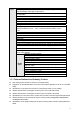
Appendix H Toxic or Hazardous Materials or Elements Toxic or Hazardous Materials or Elements Component Name Pb Hg Cd Cr VI PBB PBDE Sheet Metal(Case) Plastic Parts(Panel) Lithium Battery LED ż ż ż ż ż ż ż ż ż ż ż ż ż ż ż ż ż ż ż ż ż ż ż ż Touch Panel ż ż ż ż ż ż Solid HDD ż ż ż ż ż ż Circuit Board ż ż ż ż ż ż Fastener ż ż ż ż ż ż Wire and Cable/Ac Adapter Aluminum Case Accessories ż ż ż ż ż ż ż ż ż ż ż ż ż ż ż ż ż ż Note O: In