b) c) d) Figure 4-69 Select motion detect from the event type dropdown list. Select a channel from the dropdown list and then check the enable button to enable motion detect function. Click Region Select button to set motion detect zone. There are 396(PAL)/330(NTSC) small zones. The green zone is current cursor position. Grey zone is the motion detection zone. Black zone is the disarmed zone. You can click Fn button to switch between the arm mode and disarm mode.
i) j) Click Copy button to copy current setup to other channel(s). Click OK button to complete motion detect record setup. Figure 4-70 Figure 4-71 4.10.3.2 Motion Detect Snapshot a) b) c) d) From Main menu->Setting->Camera->Encode->Snapshot, you can go to snapshot interface. See Figure 4-72. In Figure 4-72, select trigger snapshot from the dropdown list and then set picture size, quality and snapshot frequency. Click OK button to save current setup.
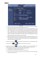
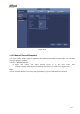
Figure 4-72 4.10.4 Alarm Record/Snapshot 4.10.4.1 Alarm Record a) Before you set alarm setup information, please go to chapter 2.3 to connect alarm input and alarm output cable (such as light, siren and etc). b) The record priority is: Alarm>Motion detect>Regular. In the main menu, from Setting->Event-> Alarm, you can see alarm setup interface. See Figure 4-73. Alarm in: Here is for you to select channel number. Event type: There are four types.
Figure 4-73 d) e) f) g) From Mani menu->Setting->Storage->Schedule, you can go to Figure 4-63. Select alarm channel, period and the record type shall be alarm. Please refer to chapter 4.10.2. Click Copy button to copy current setup to other channel(s). Click OK button to save alarm record information. 4.10.4.2 Alarm Snapshot a) b) c) d) Please refer to Step a) to step c) of chapter 4.10.3.2 to enable timing snapshot.
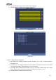
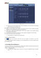
Figure 4-74 4.10.5 Manual Record/Snapshot You need to have proper rights to implement the following operations. Please make sure the HDD has been properly installed. 4.10.5.1 Manual Record a) Right click mouse and select manual record or in the main menu, Setting->Storage->Manual Record. Manual record menu is shown as in Figure 4-75. from Tips You can click Rec button on the front panel (if possible) to go to the Manual Record interface.
Figure 4-75 b) Check the box here to select manual record channel(s). You can see the corresponding indicator light on the front panel is on. Channel: It is to display device all channels. Manual: It has the highest priority. Enable corresponding channel to record no matter what period applied in the record setup. Now system is record general file. Auto: System enables auto record function as you set in chapter 4.10.
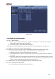
Figure 4-76 b) Click Add new holiday button, you can see an interface shown as in Figure 4-77. Here you can set holiday date name, repeat mode, start time/end time and etc. Figure 4-77 c) d) Click Add button to complete holiday setup. Now you can enable holiday setup and then click Apply button. From Main menu->setting->Storage->schedule, you can go to schedule interface.
4-78. Now you can set period and record type of holiday time. Please refer to chapter 4.10.2.1 for detailed setup information. Figure 4-78 e) Click OK button to set holiday record setup. 4.10.6.2 Holiday Snapshot Set Holiday date first. Please refer to step a) to step c) of chapter 4.10.6.1. From Main menu->Setting->Storage->Schedule, you can go to schedule interface. See Figure 4-78. Click Holiday item to set snapshot period. Set holiday snapshot type (Trigger/Regular). Please refer to chapter 4.10.2.
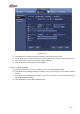
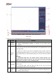
Figure 4-79 Please refer to the following sheet for more information. SN 1 Name Display window Function Here is to display the searched picture or file. Support 1/4/9/16-window playback. (It depends on the product channel amount). Search type Here you can select to search the picture or the recorded file. You can select to play from the read-write HDD, from peripheral device or from redundancy HDD.
5 6 7 8 channel selection pane. Card number search The card number search interface is shown as below. Here you can view card number/field setup bar. You can implement advanced search. Current series product supports this function. Face list Mark file list button File list switch button In 4-window playback mode: you can select 4 channels according to your requirement. In 9-window playback mode, you can switch between 1-8, 9-16 and etc channels.
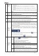
│ to begin frame by frame playback. In frame by frame playback mode, click ►/ to restore normal playback. ► Slow play In playback mode, click it to realize various slow play modes such as slow play 1, slow play 2, and etc. Fast forward In playback mode, click to realize various fast play modes such as fast play 1,fast play 2 and etc. Note: The actual play speed has relationship with the software version.
supports customized path setup. After select or create new folder, click the Start button to begin the backup operation. The record file(s) will be saved in the specified folder. Check the file again you can cancel current selection. System max supports to display 32 files from one channel. After you clip on record file, click Backup button you can save it. For one device, if there is a backup in process, you can not start a new backup operation. It is to edit the file.
17 Digital zoom When the system is in full-screen playback mode, left click the mouse in the screen. Drag your mouse in the screen to select a section and then left click mouse to realize digital zoom. You can right click mouse to exit. 18 Manually switch channel when playback During the file playback process, you can switch to other channel via the dropdown list or rolling the mouse. This function is null if there is no record file or system is in smart search process.
right corner to search records by time. See image on the left side of the Figure 4-81 For example, input time 11:00.00 and then click Search button , you can view all the record files after 11:00.00 (The records includes current time.). See image on the right side of the Figure 4-81 Double click a file name to playback. Note After you searched files, system implement accurate playback once you click Play for the first time. System does not support accurate playback for picture.
Here you can set to begin playback from previous N seconds of the mark time. Note Usually, system can playbacks previous N seconds record if there is such kind of record file. Otherwise, system playbacks from the previous X seconds when there is such as kind of record. Mark Manager Click the mark manager button on the Search interface (Figure 4-79); you can go to Mark Manager interface. See Figure 4-83. System can manage all the record mark information of current channel by default.
4.12 Backup 4.12.1 File Backup In this interface, you can backup record file to the USB device. a) Connect USB burner, USB device or portable HDD and etc to the device. b) From Main menu->Backup, you can go to the Backup interface. See Figure 4-84 Figure 4-84 c) Select backup device and then set channel, file start time and end time. d) Click add button, system begins search. All matched files are listed below. System automatically calculates the capacity needed and remained. See Figure 4-85.
Figure 4-85 h) Click backup button, system begins burning. At the same time, the backup button becomes stop button. You can view the remaining time and process bar at the left bottom. Note During backup process, you can click ESC to exit current interface for other operation (For some series product only). The system will not terminate backup process. The file name format usually is: Channel number+Record type+Time. In the file name, the YDM format is Y+M+D+H+M+S. File extension name is .dav. 4.12.
Figure 4-86 Export: Please connect the peripheral device first and then go to the following interface. Click Export button, you can see there is a corresponding ―Config_Time‖ folder. Double click the folder, you can view some backup files. Import: Here you can import the configuration files from the peripheral device to current device. You need to select a folder first. You can see a dialogue box asking you to select a folder if you are selecting a file.
Figure 4-87 b) Select log type and then set start time/end time, click Search button, you can see log time and event information. Click to view detailed log information. c) Select log items you want to save and then click backup button, you can select a folder to save them. Click Start to backup and you can see the corresponding dialogue box after the process is finish. 4.12.4 USB Device Auto Pop-up After you inserted the USB device, system can auto detect it and pop up the following dialogue box.
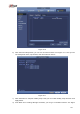
Figure 4-88 4.13 Alarm 4.13.1 Detect Alarm In the main menu, from Setting to Detect, you can see motion detect interface. See Figure 4-89.There are three detection types: motion detection, video loss, tampering. 4.13.1.1 Motion Detect After analysis video, system can generate a motion detect alarm when the detected moving signal reached the sensitivity you set here. Detection menu is shown as below. See Figure 4-89. Event type: From the dropdown list you can select motion detection type.
screen prompt, alarm upload, email will not be activated again. After 10s, if system detects another alarm signal, it can generate an alarm since the anti-dither time is out. Period: Click set button, you can see an interface is shown as in Figure 4-92. Here you can set motion detect period. System only enables motion detect operation in the specified periods. It is not for video loss or the tampering. There are two ways for you to set periods. Please note system only supports 6 periods in one day.
Figure 4-89 Figure 4-90 208
Figure 4-91 Figure 4-92 209
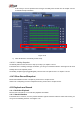
Figure 4-93 Motion detect here only has relationship with the sensitivity and region setup. It has no rel ationship with other setups. 4.13.1.2 Tampering When someone viciously masks the lens, or the output video is in one-color due to the environments light change, the system can alert you to guarantee video continuity. Tampering interface is shown as in Figure 4-94. You can enable ―Alarm output ―or ―Show message‖ function when tampering alarm occurs. Sensitivity: The value ranges from 1 to 6.
Figure 4-94 4.13.1.3 Video Loss In Figure 4-89, select video loss from the type list. You can see the interface is shown as in Figure 4-95. This function allows you to be informed when video loss phenomenon occurred. You can enable alarm output channel and then enable show message function. You can refer to chapter 4.13.1.1Motion detect for detailed information. Tips: You can enable preset/tour/pattern activation operation when video loss occurs.
Figure 4-95 4.13.2 IVS (Optional) Please make sure you are connecting to the smart network camera, otherwise you can not use IVS function! From main menu->Setting->Event, you can go to the IVS interface. It includes four interfaces: Tripwire/intrusion/object/scene. 4.13.2.1 Tripwire (Optional) Please make sure you are connecting to the smart network camera, otherwise you can not use IVS function! System generates an alarm once there is any object crossing the tripwire in the specified direction.
Figure 4-96 Check the Enable box to enable tripwire function. Click Rule setup to draw the tripwire. See Figure 4-97. Figure 4-97 Select SN (Line1/2/3/4) and direction, and then input customized rule name. Line1/2/3/4: System supports four tripwires. Each SN stands for one tripwire.
Direction ( / specified direction. / ): System can generate an alarm once there is any object crossing in the Now you can draw a rule. Left click mouse to draw a tripwire. The tripwire can be a direct line, curve or polygon. Right click mouse to complete. Click to draw filter object. Figure 4-98 Select the blue line and then use mouse to adjust zone size. Note Each rule can set two sizes (min size/max size). Once the object is smaller than the min size or larger than the max size, there is no alarm.
the icon is shown as . Click In Figure 4-92. Click button to delete a record type from one period. after one date or a holiday, you can see an interface shown as in Figure 4-93. Alarm output: when an alarm occurs, system enables peripheral alarm devices. Latch: when tripwire complete, system auto delays detecting for a specified time. The value ranges from 1-300(Unit: second) Show message: System can pop up a message to alarm you in the local host screen if you enabled this function.
Figure 4-100 Figure 4-101 4.13.2.2 Intrusion (Cross warning zone) (Optional) Please make sure you are connecting to the smart network camera, otherwise you can not use IVS function! System generates an alarm once there is any object entering or exiting the zone in the specified direction. From main menu->Setting->Event->IVS->Intrusion, the intrusion interface is shown as below. See Figure 4-102.
Figure 4-102 Check the enable box to enable intrusion function. Click Rule setup to draw the zone. See Figure 4-103. Figure 4-103 Select SN (Area1/2/3/4) and direction, and then input customized rule name. Area1/2/3/4: System supports four zones. Each SN stands for one zone. Direction ( / / ): System can generate an alarm once there is any object enter/exit (Or both) the zone. Now you can draw a rule.
Click to delete the corresponding rule. You can refer to the chapter 4.13.2.1 to set parameters. 4.13.2.3 Object Detect (Optional) Please make sure you are connecting to the smart network camera, otherwise you can not use IVS function! For the same channel, the object detect and the intrusion can not be valid at the same time. System generates an alarm when the object missing/abandoned object alarm occurs. From main menu->Setting->Event->IVS->Object, the object interface is shown as below.
Select SN (object1/2/3/4) and direction, and then input customized rule name. Object1/2/3/4: System supports four zones. Each SN stands for one zone. Direction ( / ): For icon one for the specified time.. For icon , system can generate an alarm once the object left in the , system can generate an alarm once the object is out of the zone for the specified time. Period: It refers to the object in/out the zone time. Now you can draw a rule.
4.13.3 Face Detect (Optional) Please make sure you are connecting to the smart network camera, otherwise you can not use IVS function! When camera detects human face, system can generate an alarm. From main menu->Setting->Event->Face detect, the interface is shown as in Figure 4-107. Face ROI: Check the box here, system can enhance the human face display pane. Log: Check the box here, system can record face detect log. You can refer to the chapter 4.13.2.1 t to set other parameters. Figure 4-107 4.
Threshold: It is to set intensity change threshold. The smaller the value is, the higher the sensitivity is. Log: Check the box here, system can record audio detect alarm log. You can refer to the chapter 4.13.2.1 t to set other parameters. Figure 4-108 4.13.5 Alarm output From Main menu->Setting->Event->Alarm output, you can see an interface shown as in Figure 4-109. Here is for you to set proper alarm output (Auto/manual/stop).
Figure 4-109 Please highlight icon to select the corresponding alarm output. After all the setups please click OK button, system goes back to the previous menu. 4.13.6 Alarm Setup In the main menu, from Setting->Event->Alarm, you can see alarm setup interface. Alarm in: Here is for you to select channel number. In the main menu, from Setting->Event->Alarm, you can see alarm setup interface. See Figure 4-110. There are four alarm types. See Figure 4-110 to Figure 4-113.
screen prompt, alarm upload, email will not be activated again. After 10s, if system detects another alarm signal, it can generate an alarm since the anti-dither time is out. Alarm output: The number here is the device alarm output port. You can select the corresponding ports(s) so that system can activate the corresponding alarm device(s) when an alarm occurred. Latch: When the anti-dither time ended, the channel alarm you select in the alarm output may last the specified period.
Figure 4-110 Figure 4-111 224
. Figure 4-112 Figure 4-113 225
Figure 4-114 Figure 4-115 226
Figure 4-116 Please highlight icon to select the corresponding function. After setting all the setups please click save button, system goes back to the previous menu. 4.13.7 Abnormality There are two types: Disk/Network. Disk: Disk error, no disk, no space. See Figure 4-117 and Figure 4-118. Network: Disconnection, IP conflict, MAC conflict. See Figure 4-119. Alarm output: Please select alarm activation output port (multiple choices).
Figure 4-117 Figure 4-118 228
Figure 4-119 4.14 Network 4.14.1.1 TCP/IP The single network adapter interface is shown as in Figure 4-120 and the dual network adapters interface is shown as in Figure 4-121. Network Mode : Includes multiple access, fault tolerance, and load balancing Multiple-address mode: eth0 and eth1 operate separately. You can use the services such as HTTP, RTP service via etho0 or the eth1.
IP Version: There are two options: IPv4 and IPv6. Right now, system supports these two IP address format and you can access via them. MAC address: The host in the LAN can get a unique MAC address. It is for you to access in the LAN. It is read-only. IP address: Here you can use up/down button () or input the corresponding number to input IP address. Then you can set the corresponding subnet mask the default gateway. Default gateway: Here you can input the default gateway.
Figure 4-120 Figure 4-121 4.14.1.2 Connection The connection setup interface is shown as in Figure 4-122. Max connection: system support maximal 128 users. 0 means there is no connection limit. TCP port: Default value is 37777.
UDP port: Default value is 37778. HTTP port: Default value is 80. HTTPS port: Default value is 443. RTSP port: Default value is 554. Important: System needs to reboot after you changed and saved any setup of the above four ports. Please make sure the port values here do not conflict. Figure 4-122 4.14.1.3 WIFI AP Note This function is for some series product only. 4.14.1.3.1 WIFI AP The WIFI AP interface is shown as below. See Figure 4-123.
Figure 4-123 4.14.1.3.2 Advanced Click Advanced, you can see an interface shown as below. See Figure 4-124. IPv4 address: Input WIFI AP IP address. IPv4 netmask: Input WIFI AP network mask. IPv4 gateway: Input WIFI AP gateway. Start IP/End IP: Input start IP and end IP of the network cameras. The NVR can allocate the IP addresses in the range you specified here. Upgrade: Click it to upgrade WIFI AP module.
Figure 4-124 4.14.1.4 WIFI The WIFI interface is shown as below. See Figure 4-125. Enable: Check the box here to enable WIFI function. Refresh: You can click it to search the hotspot list again. It can automatically add the information such as the password if you have set it before. Disconnect: Here you can click it to turn off the connection. Connect: Here you can click it to connect to the hotspot.
Figure 4-125 WIFI working status: Here you can view current connection status. Please note: After successful connection, you can see WIFI connection icon at the top right corner of the preview interface. When the hotspot verification type is WEP, system displays as AUTO since the device can not detect its encryption type. System does not support verification type WPA and WPA2. The display may become abnormal for the verification type and encryption type.
APN: It is the wireless connection server. It is to set you access the wireless network via which method. AUTH: It is the authentication mode. It supports PAP/CHAP. Dial number: Please input 3G network dialup number you got from your ISP. User name: It is the user name for you to login the 3G network. Password: It is the password for you to login the 3G network. Pulse interval: You can set dialup duration. Once you disable the extra stream, the connection time begins.
Figure 4-127 4.14.1.7 DDNS DDNS setup interface is shown as in Figure 4-128. You need a PC of fixed IP in the internet and there is the DDNS software running in this PC. In other words, this PC is a DNS (domain name server). In network DDNS, please select DDNS type and highlight enable item. And them please input your PPPoE name you get from you IPS and server IP (PC with DDNS). Click save button and then reboot system. Click save button, system prompts for rebooting to get all setup activated.
Figure 4-128 Please note DDNS type includes: CN99 DDNS, NO-IP DDNS, Quick DDNS, Dyndns DDNS and sysdns DDNS. All the DDNS can be valid at the same time, you can select as you requirement. Private DDNS function shall work with special DDNS server and special Professional Surveillance Software (PSS). Dahua DDNS and Client-end Introduction 1) Background Introduction Device IP is not fixed if you use ADSL to login the network. The DDNS function allows you to access the NVR via the registered domain name.
the device IP. User name: It is optional. You can input your commonly used email address. Important Do not register frequently. The interval between two registrations shall be more than 60 seconds. Too many registration requests may result in server attack. System may take back the domain name that is idle for one year. You can get a notification email before the cancel operation if your email address setup is OK. 4.14.1.
Figure 4-129 Figure 4-130 4.14.1.9 IP Filter IP filter interface is shown as in Figure 4-131. You can add IP in the following list. The list supports max 64 IP addresses. System supports valid address of IPv4 and IPv6. Please note system needs to check the validity of all IPv6 addresses and implement optimization. After you enabled trusted sites function, only the IP listed below can access current NVR. If you enable blocked sites function, the following listed IP addresses can not access current NVR.
Type: You can select trusted site and blacklist from the dropdown list. You can view the IP address on the following column. Start address/end address: Select one type from the dropdown list, you can input IP address in the start address and end address. Now you can click Add IP address or Add IP section to add. a) For the newly added IP address, it is in enable status by default. Remove the √ before the item, and then current item is not in the list. b) System max supports 64 items.
Figure 4-132 4.14.1.10 Email The email interface is shown as below. See Figure 4-133. SMTP server: Please input your email SMTP server IP here. Port: Please input corresponding port value here. User name: Please input the user name to login the sender email box. Password: Please input the corresponding password here. Sender: Please input sender email box here. Title: Please input email subject here. System support English character and Arabic number. Max 32-digit.
Figure 4-133 4.14.1.11 FTP You need to download or buy FTP service tool (such as Ser-U FTP SERVER) to establish FTP service. Please install Ser-U FTP SERVER first. From ―start‖ -> ―program‖ -> Serv-U FTP Server -> Serv-U Administrator. Now you can set user password and FTP folder. Please note you need to grant write right to FTP upload user. See Figure 4-134. Figure 4-134 You can use a PC or FTP login tool to test setup is right or not. For example, you can login user ZHY to FTP://10.10.7.
or not. See Figure 4-135. Figure 4-135 System also supports upload multiple NVRs to one FTP server. You can create multiple folders under this FTP. FTP interface is shown as in Figure 4-136. Please highlight the icon in front of Enable to activate FTP function. Here you can input FTP server address, port and remote directory. When remote directory is null, system automatically create folders according to the IP, time and channel. User name and password is the account information for you to login the FTP.
4.14.1.12 SNMP SNMP is an abbreviation of Simple Network Management Protocol. It provides the basic network management frame of the network management system. The SNMP widely used in many environments. It is used in many network device, software and system. You can set in the following interface. See Figure 4-137. Figure 4-137 Please enable the SNMP function. Use the corresponding software tool (MIB Builder and MG-SOFT MIB Browser.
Figure 4-138 Here you can set a multiple cast group. Please refer to the following sheet for detailed information. IP multiple cast group address -224.0.0.0-239.255.255.255 -―D‖ address space The higher four-bit of the first byte=‖1110‖ Reserved local multiple cast group address -224.0.0.0-224.0.0.255 -TTL=1 When sending out telegraph -For example 224.0.0.1 All systems in the sub-net 224.0.0.2 All routers in the sub-net 224.0.0.4 DVMRP router 224.0.0.5 OSPF router 224.0.0.
After you logged in the Web, the Web can automatically get multiple cast address and add it to the multiple cast groups. You can enable real-time monitor function to view the view. Please note multiple cast function applies to special series only. 4.14.1.14 Alarm Centre This interface is reserved for you to develop. See Figure 4-139. Figure 4-139 4.14.1.15 Auto register This function allows the device to auto register to the proxy you specified.
Figure 4-140 2) The proxy server software developed from the SDK. Please open the software and input the global setup. Please make sure the auto connection port here is the same as the port you set in the previous step. 3) Now you can add device. Please do not input default port number such as the TCP port in the mapping port number. The device ID here shall be the same with the ID you input in Figure 4-140. Click Add button to complete the setup. 4) Now you can boot up the proxy server.
Figure 4-141 Android: Open Google Play app in your smart phone. Search gDMSS Lite or gDMSS Plus, download it and install. iOS: Open App Store app in your smart phone. Search iDMSS Lite or iDMSS Plus, download it and install. Please follow the steps listed below. Open App; tap Tap Tap Device manager button, you can use several modes (P2P/DDNS/IP and etc) to add the device. to go to the Liv preview. at the top left corner, you can see the main menu. Click to save current setup.
Figure 4-142 4.14.1.17 Easy Space This function allows you to upload motion detect record or snapshot image to the dropbox and etc. The easy space interface is shown as below. See Figure 4-143. Please select the easy space address from the dropdown list and then input corresponding user name and password.
Note: The uploaded file is for sub stream only. Please go to record control interface (main stream->setting->Storage->Record) and then select sub stream. The easy space function uses upload bandwidth. Usually the recommended upload bandwidth shall be more than 512kbps and please make sure the network is stable. The easy space upload data adopts safe SSL encryption connection. Please enable 1-channel to upload in case this function occupies too much CPU. 4.14.1.
You can view all connected network adapter names (including Ethernet, PPPoE, WIFI, and 3G), you can click the button on the right panel to begin Sniffer. Click the grey stop button to stop. Please note system can not Sniffer several network adapters at the same time. After Sniffer began, you can exit to implement corresponding network operation such as login WEB, monitor. Please go back to Sniffer interface to click stop Sniffer. System can save the packets to the specified path.
Figure 4-146 4.15 HDD Setup Here you can view HDD information such as type, status, total capacity, record time and etc. The operation includes format, resume from error, change HDD property (Read write, Read-only). Here you can also set alarm and HDD storage position. 4.15.1 Format a) From Mani-menu->Setting->Storage->HDD Manager, you can go to HDD management interface. See Figure 4-147.
Figure 4-147 b) Select a HDD and then select format from the dropdown list. Click Execute button. c) Click OK button to complete the setup. You can see system needs to restart to activate current setup. 4.15.2 HDD Information Here is to list hard disk type, total space, free space, and status. See Figure 4-148. ○ means current HDD is normal.. - means there is no HDD. If disk is damaged, system shows as ―?‖. Please remove the broken hard disk before you add a new one.
Figure 4-148 In Figure 4-148, click one HDD item, the S.M.A.R.T interface is shown as in Figure 4-149.
Parameter Function SATA 1 here means there is 1 HDD. For different series product, the max HDD amount may vary, When HDD is working properly, system is shown as O. . ―_‖ means there is no HDD. SN You can view the HDD amount the device connected to; ﹡ means the second HDD is current working HDD. Type The corresponding HDD property. Total space The HDD total capacity. Free space The HDD free capacity. Status HDD can work properly or not. Bad track Display there is bad track or not.
Figure 4-150 Please select the correspond group from the dropdown list and then click Apply button. Click main stream/sub stream/snapshot button to set corresponding HDD group information. See Figure 4-151 through Figure 4-153.
Figure 4-152 Figure 4-153 4.15.4 HDD Detect Note This function is for some series product only. The HDD detect function is to detect HDD current status so that you can clearly understand the HDD performance and replace the malfunction HDD.
There are two detect types: Quick detect is to detect via the universal system files. System can quickly complete the HDD scan. If you want to use this function, please make sure the HDD is in use now. If the HDD is removed from other device, please make sure the write-data once was full after it installed on current device. Global detect adopts Windows mode to scan. It may take a long time and may affect the HDD that is recording. 4.15.4.
Figure 4-155 Click View, you can see the detailed information such as detect result, backup and S.M.A.R.T. See Figure 4-156 and Figure 4-157.
Figure 4-157 4.15.5 RAID Manager Important Please make sure your purchased product support the RAID function, otherwise you can not see the following interface. Right now, RAID supports Raid0, Raid1, Raid5, Raid6, and Raid10. Local hotspare supports Raid1, Raid5, Raid6, and Raid10. 4.15.5.1 RAID Config It is for you to manage RAID HDD. It can display RAID name, type, free space, total space, status and etc. Here you can add/delete RAID HDD.
Figure 4-158 4.15.5.2 Hotspare disks Click Hotspare disks tab name, you can add the hot spare HDD. See Figure 4-159. The type includes two options: Global: It is global hotspare disk. When any RAID becomes degrading, it can replace and build the RAID. Local: It is local hotspare disk. When the specified RAID becomes degrading, it can replace and build the RAID. Select a hot spare device and then click Delete button. Click Apply button to delete.
Figure 4-159 4.16 Basic Setups Set NVR basic setup, device setup and other setups. 4.16.1 Device Setup From Main menu->Setting->System->General, you can go to the general interface. See Figure 4-161. Pack duration: Here is for you to specify record duration. The value ranges from 0 to 120 minutes. Default value is 60 minutes. Device ID: Please input a corresponding device name here.
IPC Time Sync: You can input an interval here to synchronize the NVR time and IPC time. Startup wizard: Once you check the box here, system will go to the startup wizard directly when the system restarts the next time. Otherwise, it will go to the login interface. Mouse sensitivity: You can set double click speed via dragging the slide bard. You can Click Default button to restore default setup. Enable IVS: Check the box to enable IVS function, system can display IVS rule on the preview interface.
Figure 4-161 4.16.3 Holiday Please refer to chapter 4.10.6 for detailed information. 4.17 Device Maintenance and Manager 4.17.1 System Info 4.17.1.1 Version From main menu->Info->System->version, you can go to version interface. Here is for you to view some version information. See Figure 4-162. Please note the following figure for reference only.
Figure 4-162 4.17.1.2 BPS Here is for you to view current video bit rate (kb/s) and resolution. See Figure 4-163. Figure 4-163 4.17.1.3 Online User Here is for you manage online users connected to your NVR. See Figure 4-164.
You can click button to disconnect or block one user if you have proper system right. System detects there is any newly added or deleted user in each five seconds and refresh the list automatically. Figure 4-164 4.17.1.4 Remote Device Information From main menu->info-Event, here you can view the channel status of the remote device, connection log and etc. See Figure 4-165.
Figure 4-165 4.17.1.5 Remote 4.17.1.5.1 Device Status Here you can view the IPC status of the corresponding channel such as motion detect, video loss, tampering, alarm and etc. See Figure 4-166. IPC status: : Front-end does not support. event from current front-end. : Front-end supports. Connection status: : Connection failed. Refresh: Click it to get latest front-end channel status. : Connection succeeded.
Figure 4-166 4.17.1.5.2 Firmware It is to view channel, IP address, manufacturer, type, system version, SN, video input, audio input, external alarm and etc. See Figure 4-167.
4.17.2 Log From Main menu->Info->Log, you can go to the following interface. See Figure 4-168. Start time/end time: Pleased select start time and end time, then click search button. You can view the log files in a list. System max displays 100 logs in one page. It can max save 1024 log files. Please use page up/down button on the interface or the front panel to view more. Tips Double click a log item to view its detailed information. See Figure 4-169. Click PgUp/PgDn to view more logs.
4.17.3 Voice Note This function is for some series product only. The audio function is to manage audio files and set schedule play function. It is to realize audio broadcast activation function. 4.17.3.1.1 File Manage Here you can add audio file, listen to the audio file, or rename/delete audio file. Here you can also set audio volume. See Figure 4-170. Figure 4-170 Click Add button, you can add audio file and import the audio file via the USB device. The audio file format shall be MP3 or PCM.
Figure 4-171 4.17.3.1.2 Schedule It is to set schedule broadcast function. You can play the different audio files in the specified periods. See Figure 4-172. Figure 4-172 4.17.4 Account Here is for you to implement account management. See Figure 4-173.
Modify user Add group Modify group Modify password. For account management please note: For the user account name and the user group, the string max length is 6-byte. The backspace in front of or at the back of the string is invalid. There can be backspace in the middle. The string includes the valid character, letter, number, underline, subtraction sign, and dot. The default user amount is 64 and the default group amount is 20. System account adopts two-level management: group and user.
4.17.4.1.1 Add User Click modify user button in Figure 4-173 , the interface is shown as in Figure 4-174. Please input the user name, password, select the group it belongs to from the dropdown list. Then you can check the corresponding rights for current user. For convenient user management, usually we recommend the general user right is lower than the admin account. Username: admin. Password: admin. (administrator, local and network) Username: 888888. Password: 888888.
Figure 4-175 Click Set button, you can set six periods in one day. See Figure 4-176. Check the box after the period, you can enable current setup.
4.17.4.1.2 Modify user Click , you can go to the following interface to change user information. See Figure 4-177. For admin, 888888, and default (hidden user), you can not change period setup. Figure 4-177 4.17.4.1.3 Change Password In Figure 4-177, check the Modify password box, you can change password. Please input old password, and then input new password twice to confirm. The password can contain 32-byte and the space at the begin or at the end of the password are null.
Figure 4-178 Click add group button in Figure 4-178 , the interface is shown as below. See Figure 4-179. Here you can input group name and then input some memo information if necessary. There are total 98 rights such as control panel, shut down, real-time monitor, playback, record, record file backup, PTZ, user account, system information view, alarm input/output setup, system setup, log view, clear log, upgrade system, control device and etc.
4.17.4.1.5 Security Question The security question is shown as below. See Figure 4-180. Here you can change security questions. Figure 4-180 4.17.5 Update 4.17.5.1 Local Update From Mani menu->Setting->Info->Update, you can go to the following interface. See Figure 4-181. a) Insert USB device that contain the upgrade file. b) Click Start button and then select the .bin file. c) You can see the corresponding dialogue box after the update process is complete.
Figure 4-181 4.17.5.2 Uboot When device is booting up, it can auto detect the USB device and the update file on it. It can auto update once there is proper upgrade file. Important USB device root directory shall have ―u-boot.bin.img‖ and ―update.img‖ files. USB device shall be FAT32 mode. For 4X series product, it only updates ―update.img‖. The ―update.img‖ shall be renamed as ―recovery.img‖ and is saved on the root directory. USB device shall be on the USB 2.
Please highlight icon to select the corresponding function. After all the setups please click OK button, system goes back to the previous menu. Warning! After you use default function, some your customized setup may lose forever! Please think twice before you begin the operation! Figure 4-182 4.17.7 RS232 From Main menu->Setting->System->RS232, RS232 interface is shown as below. There are five items. See Figure 4-183. Function: There are various devices for you to select.
Parity: None After completing all the setups please click save button, system goes back to the previous menu. Figure 4-183 4.17.8 Auto Maintain Here you can set auto-reboot time and auto-delete old files setup. You can set to delete the files for the specified days. See Figure 4-184. You can select proper setup from dropdown list. After all the setups please click save button, system goes back to the previous menu.
4.17.9 Logout /Shutdown/Restart From Mani menu->Operation->Shutdown, you can see an interface shown as in Figure 4-185. Shutdown: System shuts down and turns off power. Logout: Log out menu. You need to input password when you login the next time. Restart: reboot device. If you shut down the device, there is a process bar for your reference, system waits for 3 seconds and then shut down (You can not cancel). Please note, sometimes you need to input the proper password to shut down the device.
5 Web Operation 5.1 General Introduction The device web provides channel monitor menu tree, search, alarm setup, system setup, PTZ control and monitor window and etc. Important The following operation is based on 32-channel series device. 5.1.1 Preparation Before log in, please make sure: Network connection is right NVR and PC network setup is right. Please refer to network setup(main menu->setting->network) Use order ping ***.***.***.***(* NVR IP address) to check connection is OK or not.
c) Thirdly, according to the --- map, system can know the previous mapping channel of current PoE port. System can select current channel if it is free. Otherwise, it goes to the next step: d) Fourthly, system goes to find the first idle channel it can get. Generally speaking, once you insert PoE, system follow the steps listed above to find the channel available. 4) When you insert PoE, all channels are in use now.
Figure 5-2 After installation, the interface is shown as below. See Figure 5-3. Figure 5-3 Please input your user name and password. Default factory name is admin and password is admin. Note: For security reasons, please modify your password after you first login. 5.2 LAN Mode For the LAN mode, after you logged in, you can see the main window. See Figure 5-9. This main window can be divided into the following sections.
Section 1: there are six function buttons: Live(chapter 0), setup (chapter 5.8), info (Chapter 5.9), playback (chapter 5.10), alarm (chapter 5.11), and logout (chapter 5.12). Section 2: There are monitor channels successfully connected to the NVR. Please refer to Figure 5-4 for main stream and extra stream switch information. Figure 5-4 Section 3: Open all. Open all button is to enable/disable all-channel real-time monitor. Here you can select main stream/sub stream too. See Figure 5-5.
The Web can playback the saved (Extension name is dav) files in the PC-end. Click local play button, system pops up the following interface for you to select local play file. See Figure 5-8. Figure 5-8 Section 7:Zero-channel encoding. Please refer to chapter 5.6 for detailed information. Section 8: PTZ operation panel. Please refer to chapter 5.4 for detailed information. Section 9: Image setup and alarm setup. Please refer to chapter 5.5 for detailed information.
In section 2, left click the channel name you want to view, you can see the corresponding video in current window. On the top left corner, you can view device IP(172.11.10.11), channel number(1), network monitor bit stream(2202Kbps) and stream type(M=main stream, S=sub stream). See Figure 5-10. 1 2 3 4 Figure 5-10 On the top right corner, there are six unction buttons. See Figure 5-11.
Parameter Function Preset Select Preset from the dropdown list. Turn the camera to the corresponding position and Input the preset value. Click Add button to add a preset. Tour Select Tour from the dropdown list. Input preset value in the column. Click Add preset button, you have added one preset in the tour. Repeat the above procedures you can add more presets in one tour. Or you can click delete preset button to remove one preset from the tour.
5.5 Image/Alarm-out Select one monitor channel video and then click Image button in section 9, the interface is shown as Figure 5-13. 5.5.1 Image Here you can adjust its brightness, contrast, hue and saturation. (Current channel border becomes green). Or you can click Reset button to restore system default setup. Figure 5-13 5.5.2 Alarm output Here you can enable or disable the alarm signal of the corresponding port. See Figure 5-14. Figure 5-14 5.
Figure 5-15 5.7 WAN Login In WAN mode, after you logged in, the interface is shown as below. See Figure 5-16. Figure 5-16 Please refer to the following contents for LAN and WAN login difference. 1) In the WAN mode, system opens the main stream of the first channel to monitor by default. The open/close button on the left pane is null. 2) You can select different channels and different monitor modes at the bottom of the interface.
Figure 5-17. Figure 5-17 Important The window display mode and the channel number are by default. For example, for the 16-channel, the max window split mode is 16. 3) Multiple-channel monitor, system adopts extra stream to monitor by default. Double click one channel, system switches to single channel and system uses main stream to monitor. You can view there are two icons at the left top corner of the channel number for you reference. M stands for main stream. S stands for sub stream (extra stream).
Figure 5-18 Figure 5-19 Please refer to the following sheet for parameter information. Parameter Function Device search Click Device search button, you can view the searched device information on the list. It includes device IP address, port, device name, manufacturer and type. Add Select a device in the list and then click Add button, system can connect the device automatically and add it to the Added device list. Or you can double click one item in the list to add a device.
Parameter Delete Function Click , you can delete the remote connection of the corresponding channel. Type There are two connection types. You can use the network to connect to the camera or use the WIFI. The means current network camera connection mode is general; the means current network camera mode is hotspot. Delete Select a device in the Added device list and then click Delete button, system can disconnect the device and remove it from the Added device list.
Figure 5-20 Please refer to the following sheet for detailed information. Parameter Function Channel Please select a channel from the dropdown list. Period It divides one day (24 hours) to two periods. You can set different hue, brightness, and contrast for different periods. Hue It is to adjust monitor video brightness and darkness level. The default value is 50. The bigger the value is, the large the contrast between the bright and dark section is and vice versa.
attractive if the value is too low. The recommended value ranges from 40 to 60. Gain The gain adjust is to set the gain value. The smaller the value is, the low the noise is. But the brightness is also too low in the dark environments. It can enhance the video brightness if the value is high. But the video noise may become too clear. White level It is to enhance video effect. Color mode It includes several modes such as standard, color.
video according to the device feature (The general bright of the video or there is IR light or not.) B/W: The device outputs the black and white video. Sensor: It is to set when there is peripheral connected IR light. 5.8.1.3 Encode 5.8.1.3.1 Encode The encode interface is shown as below. See Figure 5-21. Figure 5-21 Please refer to the following sheet for detailed information. Parameter Function Channel Please select a channel from the dropdown list.
Frame Rate Bit Rate PAL:1~25f/s;NTSC:1~30f/s. Main stream: You can set bit rate here to change video quality. The large the bit rate is, the better the quality is. Please refer to recommend bit rate for the detailed information. Extra stream: In CBR, the bit rate here is the max value. In dynamic video, system needs to low frame rate or video quality to guarantee the value. The value is null in VBR mode.
Image size It is the same with the resolution of the main stream. Quality It is to set the image quality. There are six levels. Interval It is to set snapshot frequency. The value ranges from 1s to 7s. Or you can set customized value. The max setup is 3600s/picture. Click it; you can copy current channel setup to other channel(s). Copy 5.8.1.3.3 Video Overlay The video overlay interface is shown as in Figure 5-23. Figure 5-23 Please refer to the following sheet for detailed information.
The storage path interface is shown as in Figure 5-24. Here you can set snap image saved path ( ( in the preview interface) and the record storage path in the preview interface).The default setup is C:\PictureDownload and C:\RecordDownload. Please click the Save button to save current setup. Figure 5-24 5.8.1.4 Channel Name Here you can set channel name. See Figure 5-25. Figure 5-25 5.8.1.5 IPC Upgrade This interface is to upgrade network camera. See Figure 5-26.
Figure 5-26 5.8.2 Network 5.8.2.1 TCP/IP The TCP/IP interface is shown as in Figure 5-27. Figure 5-27 Please refer to the following sheet for detailed information. Parameter Function Mode There are two modes: static mode and the DHCP mode. The IP/submask/gateway are null when you select the DHCP mode to auto search the IP.
IP/submask/gateway manually. If you select the DHCP mode, you can view the IP/submask/gateway from the DHCP. If you switch from the DHCP mode to the static mode, you need to reset the IP parameters. Besides, IP/submask/gateway and DHCP are read-only when the PPPoE dial is OK. Mac Address It is to display host Mac address. IP Version It is to select IP version. IPV4 or IPV6. You can access the IP address of these two versions.
number if necessary. UDP port The default value is 37778. You can input the actual port number if necessary. HTTP port The default value is 80. You can input the actual port number if necessary. HTTPS The default value is 443. You can input the actual port number if necessary. RTSP port The default value is 554. 5.8.2.3 WIFI AP Please note this function is for some series only. 5.8.2.3.1 General Setup The WIFI AP interface is shown as in Figure 5-29.
Click Advanced butto, the interface is shown as below. See Figure 5-30. Figure 5-30 Please refer to the following sheet for detailed information. Parameter Function IPv4 address Input WIFI AP IP address. IPv4 netmask Input WIFI AP network mask. IPv4 gateway Input WIFI AP gateway. Start IP/End IP Input start IP and end IP. The NVR can allocate the IP address in the range you specified here. Upgrade Click it to upgrade WIFI AP module. 5.8.2.
Figure 5-31 Please check the box to enable WIFI function and then click the Search SSID button. Now you can view all the wireless network information in the following list. Double click a name to connect to it. Click Refresh button, you can view latest connection status. 5.8.2.5 3G 5.8.2.5.1 CDMA/GPRS The CDMA/GPRS interface is shown as in Figure 5-32. Figure 5-32 Please refer to the following sheet for detailed information.
Parameter Function WLAN type Here you can select 3G network type to distinguish the 3G module from different ISP. The types include WCDMA, CDMA1x and etc. APN/Dial No. Here is the important parameter of PPP. Authorization It includes PAP,CHAP,NO_AUTH. Pulse interval It is to set time to end 3G connection after you close extra stream monitor. For example, if you input 60 here, system ends 3G connection after you close extra stream monitor 60 seconds.
5.8.2.6 PPPoE The PPPoE interface is shown as in Figure 5-34. Input the PPPoE user name and password you get from the IPS (internet service provider) and enable PPPoE function. Please save current setup and then reboot the device to get the setup activated. Device connects to the internet via PPPoE after reboot. You can get the IP address in the WAN from the IP address column. Please note, you need to use previous IP address in the LAN to login the device.
Parameter Function Server IP DDNS server IP address Server Port DDNS server port. Domain Name Your self-defined domain name. User The user name you input to log in the server. Password The password you input to log in the server. Update period Device sends out alive signal to the server regularly. You can set interval value between the device and DDNS server here. Dahua DDNS and Client-end Introduction 1) Background Introduction Device IP is not fixed if you use ADSL to login the network.
Figure 5-36 5.8.2.9 Email The email interface is shown as in Figure 5-37. Figure 5-37 Please refer to the following sheet for detailed information. Parameter Function Enable Please check the box here to enable email function. SMTP Server Input server address and then enable this function. Port Default value is 25. You can modify it if necessary.
Parameter Function Anonymity For the server supports the anonymity function. You can auto login anonymously. You do not need to input the user name. password and the sender information. User Name The user name of the sender email account. Password The password of sender email account. Sender Sender email address. Authentication (Encryption mode) You can select SSL or none. Subject Input email subject here.
Figure 5-38 Please refer to the following sheet for detailed information. Parameter Function PAT Check the corresponding box to enable PAT function. Status Display UPnP function status. Port mapping list It is corresponding to the UPnP mapping information on the router. Check the box before the service name to enable current PAT service. Otherwise, the service is null. Service name:Customized name. Protocol:Protocol type. Internal port:The port mapped to the port.
Figure 5-39 Please refer to the following sheet for detailed information. Parameter Function SNMP Port The listening port of the proxy program of the device. It is a UDP port not a TCP port. The value ranges from 1 to 65535. The default value is 161 Read Community It is a string. It is a command between the manage process and the proxy process. It defined the authentication, access control and the management relationship between one proxy and one group of the managers.
packet, multiple-cast is the best option to reduce the broad width and the CPU load. The source host can just send out one data to transit. This function also depends on the relationship of the group member and group of the outer. Figure 5-40 5.8.2.13 Auto Register The auto register interface is shown as below. See Figure 5-41. This function allows the device to auto register to the proxy you specified. In this way, you can use the client-end to access the NVR and etc via the proxy.
Figure 5-42 5.8.2.15 HTTPS In this interface, you can set to make sure the PC can successfully login via the HTTPS. It is to guarantee communication data security. The reliable and stable technology can secure the user information security and device safety. See Figure 5-43. Note You need to implement server certificate again if you have changed device IP. You need to download root certificate if it is your first time to use HTTPS on current PC. Figure 5-43 5.8.2.15.
Figure 5-44 You can see the corresponding prompt. See Figure 5-45. Now the server certificate is successfully created. Figure 5-45 5.8.2.15.2 Download root certificate In Figure 5-43, click button, system pops up a dialogue box. See Figure 5-46. Figure 5-46 Click Open button, you can go to the following interface. See Figure 5-47.
Figure 5-47 Click Install certificate button, you can go to certificate wizard. See Figure 5-48. Figure 5-48 Click Next button to continue. Now you can select a location for the certificate. See Figure 5-49.
Figure 5-49 Click Next button, you can see the certificate import process is complete. See Figure 5-50. Figure 5-50 Click Finish button, you can see system pops up a security warning dialogue box. See Figure 5-51.
Click Yes button, system pops up the following dialogue box, you can see the certificate download is complete. See Figure 5-52. Figure 5-52 5.8.2.15.3 View and set HTTPS port From Setup->Network->Connection, you can see the following interface. See Figure 5-53. You can see HTTPS default value is 443. Figure 5-53 5.8.2.15.4 Login Open the browser and then input https://xx.xx.xx.xx:port. xx.xx.xx.xx: is your device IP or domain mane. Port is your HTTPS port.
Figure 5-54 5.8.3 Event 5.8.3.1 Video detect 5.8.3.1.1 Motion Detect After analysis video, system can generate a video loss alarm when the detected moving signal reached the sensitivity you set here. The motion detect interface is shown as in Figure 5-55.
Figure 5-55 Figure 5-56 320
Figure 5-57 Figure 5-58 Figure 5-59 321
Figure 5-60 Please refer to the following sheet for detailed information. Parameter Function Enable You need to check the box to enable motion detection function. Please select a channel from the dropdown list. Period Motion detection function becomes activated in the specified periods. See Figure 5-56. There are six periods in one day. Please draw a circle to enable corresponding period. Click OK button, system goes back to motion detection interface, please click save button to exit.
Parameter Function Buzzer Check the box here to enable this function. The buzzer beeps when an alarm occurs. Alarm upload System can upload the alarm signal to the centre (Including alarm centre. Message When 3G network connection is OK, system can send out a message when motion detect occurs. Send Email If you enabled this function, System can send out an email to alert you when an alarm occurs. Tour You need to click setup button to select tour channel.
5.8.3.1.3 Tampering The tampering interface is shown as in Figure 5-62. After analysis video, system can generate a tampering alarm when the detected moving signal reached the sensitivity you set here. For detailed setups, please refer to chapter 5.8.3.1.1 motion detect for detailed information. Figure 5-62 5.8.3.2 IVS (Optional) Please make sure you are connecting to the smart network camera, otherwise you can not use IVS function! From main menu->Setup->Event->IVS, you can go to the IVS interface.
Figure 5-63 Check the Tripwire box to enable tripwire function. Select SN (Line1/2/3/4) and direction, and then input customized rule name. No. and Line1/2/3/4: System supports four tripwires. Each SN stands for one tripwire. Direction: There are three options: A->B, B->A, both. System can generate an alarm once there is any object crossing in the specified direction. Now you can draw a rule. Click Draw rule button and then left click mouse to draw a tripwire.
Click to draw filter object. See Figure 5-65. Figure 5-65 Select the blue line and then use mouse to adjust zone size. Note Each rule can set two sizes (min size/max size). Once the object is smaller than the min size or larger than the max size, there is no alarm. Please make sure the max size is larger than the min size. Click Ok to complete the rule setup. For detailed setups, please refer to chapter 5.8.3.1.1 motion detect for detailed information. 5.8.3.2.
Figure 5-66 Check the Intrusion box to enable intrusion function. Select SN (Area1/2/3/4) and direction, and then input customized rule name. No. and Area1/2/3/4: System supports four zones. Each SN stands for one zone. Direction: There are three options: A->B, B->A, both. System can generate an alarm once there is any object enter/exit (Or both) the zone. Now you can draw a rule.
Figure 5-67 For detailed setups, please refer to chapter 5.8.3.1.1 motion detect for detailed information. 5.8.3.2.3 Object Detect Please make sure you are connecting to the smart network camera, otherwise you can not use IVS function! For the same channel,the object detect and the intrusion can not be valid at the same time. From main menu->Setup->Event->IVS->Object, the object interface is shown as below. See Figure 5-68.
Check the Object box to enable object detect function. Select SN (object1/2/3/4) and rule type, and then input customized rule name. No. and Object1/2/3/4: System supports four zones. Each SN stands for one zone. Rule type: Please select from the dropdown list. There are two types: Missing object detect/abandoned object detect. Period: It refers to the object in/out the zone time. Click to draw the rule. See Figure 5-69. Figure 5-69 Now you can draw a rule.
Figure 5-70 For detailed setups, please refer to chapter 5.8.3.1.1 motion detect for detailed information. 5.8.3.3 Face Detect (Optional) Please make sure you are connecting to the smart network camera, otherwise you can not use IVS function! When camera detects human face, system can generate an alarm. From main menu->Setup->Event->Face detect, the interface is shown as in Figure 5-71. Enable face boost: Check the box here, system can enhance the human face display pane.
5.8.3.4 Audio Detect (Optional) Please make sure you are connecting to the smart network camera, otherwise you can not use IVS function! System can generate an alarm once it detect the audio input is abnormal or audio volume changes. From main menu->Setup->Event->Audio detect, you can see an interface shown as in Figure 5-72. Input abnormal: Check the box here, system can generate an alarm once the audio input is abnormal.
Figure 5-73 Figure 5-74 332
Figure 5-75 Please refer to the following sheet for detailed information. Parameter Function Enable You need to check the box to enable this function. Please select a channel from the dropdown list. Period This function becomes activated in the specified periods. There are six periods in one day. Please draw a circle to enable corresponding period. Select date. If you do not select, current setup applies to today only. You can select all week column to apply to the whole week.
Parameter Function Show message System can pop up a message to alarm you in the local host screen if you enabled this function. Buzzer Check the box here to enable this function. The buzzer beeps when an alarm occurs. Alarm upload System can upload the alarm signal to the centre (Including alarm centre). Send Email If you enabled this function, System can send out an email to alert you when an alarm occurs. Tour You need to click setup button to select tour channel.
setup. For setup information, please refer to chapter 5.8.3.5.1. Figure 5-77 5.8.3.5.4 IPC Offline Alarm The IPC offline alarm interface is shown as in Figure 5-78. System can generate an alarm once the network camera is offline. For setup information, please refer to chapter 5.8.3.5.1.
5.8.3.6 Abnormality It includes six types: No disk, disk error, disks no space, disconnect, IP conflict, MAC conflict. See Figure 5-79 through Figure 5-84.
Figure 5-83 Figure 5-84 Please refer to the following sheet for detailed information. Parameter Function Event Type The abnormal events include: No disk, disk error, disk no space, net disconnection, IP conflict and MAC conflict. You can set one or more items here. Less than: You can set the minimum percentage value here (For disk not space only). The device can alarm when capacity is not sufficient. You need to draw a circle to enable this function.
Parameter Function Buzzer Check the box here to enable this function. The buzzer beeps when an alarm occurs. 5.8.4 Storage 5.8.4.1 Schedule In this interfaces, you can add or remove the schedule record setup. See Figure 5-85. There are four record modes: general (auto), motion detect, alarm and MD&alarm. There are six periods in one day. You can view the current time period setup from the color bar. Green color stands for the general record/snapshot.
Figure 5-87 Please refer to the following sheet for detailed information. Parameter Function Channel Please select a channel from the dropdown list. Pre-record Please input pre-record time here. The value ranges from 0 to 30. Redundancy Check the box here to enable redundancy function. Please note this function is null if there is only one HDD. Snapshot Check the box here to enable snapshot function. Holiday Check the box here to enable holiday function.
Parameter Function 5/6/7. If you want to save current setup of channel 1 to all channels, you can click the first box ―ALL‖. Click the OK button to save current copy setup. Click the OK button in the Encode interface, the copy function succeeded. 5.8.4.2 HDD Manager 5.8.4.2.1 Local Storage The local interface is shown as in Figure 5-88. Here you can see HDD information. You can also operate the read-only, read-write, redundancy (if there are more than on HDD) and format operation. Figure 5-88 5.8.4.2.
Figure 5-90 5.8.4.3 Record Control The interface is shown as in Figure 5-91. Figure 5-91 Please refer to the following sheet for detailed information. Parameter Function Channel Here you can view channel number. The number displayed here is the max channel amount of your device. Status There are three statuses: schedule, manual and stop. Schedule System enables auto record function as you set in record schedule setup (general, motion detect and alarm).
Manual It has the highest priority. Enable corresponding channel to record no matter what period applied in the record setup. Stop Stop current channel record no matter what period applied in the record setup. Start all/ stop all Check the corresponding All button, you can enable or disable all channels record. 5.8.4.4 RAID Manager Important Please make sure your purchased product support the RAID function, otherwise you can not see the following interface. 5.8.4.4.
Figure 5-93 5.8.4.5 Storage 5.8.4.5.1 Main Stream The main stream interface is shown as in Figure 5-94. Here you can set corresponding HDD group to save main stream. Figure 5-94 5.8.4.5.2 Sub Stream The sub stream interface is shown as in Figure 5-95. Here you can set corresponding HDD group to save sub stream.
Figure 5-95 5.8.4.5.3 Snapshot The snapshot interface is shown as in Figure 5-96. Here you can set corresponding HDD group to save snapshot picture. Figure 5-96 5.8.5 Setting 5.8.5.1 General The general interface includes general, date/time and holiday setup. 5.8.5.1.1 General The general interface is shown as in Figure 5-97.
Please refer to the following sheet for detailed information. Parameter Function Device ID It is to set device name. Device No. It is device channel number. Language You can select the language from the dropdown list. Please note the device needs to reboot to get the modification activated. Video Standard This is to display video standard such as PAL. HDD full Here is for you to select working mode when hard disk is full. There are two options: stop recording or rewrite.
Time Format There are two options: 24-H and 12-H. Time zone The time zone of the device. System time It is to set system time. It becomes valid after you set. Sync PC You can click this button to save the system time as your PC current time. DST Here you can set day night save time begin time and end time. You can set according to the date format or according to the week format. NTP You can check the box to enable NTP function. NTP server You can set the time server address.
5.8.5.2.1 User name In this interface you can add/remove user and modify user name. See Figure 5-100. Figure 5-100 Add user: It is to add a name to group and set the user rights. See Figure 5-101. There are three default users: admin/888888 and hidden user ―default‖. Hidden user ―default‖ is for system interior use only and can not be deleted. When there is no login user, hidden user ―default‖ automatically login.
Modify user It is to modify the user property, belonging group, password and rights. See Figure 5-102. Modify password It is to modify the user password. You need to input the old password and then input the new password twice to confirm the new setup. Please click the OK button to save. Please note, the password ranges from 1-digit to 6-digit. It shall include the number only. For the user of the account rights, he can modify the password of other users. Figure 5-102 5.8.5.2.
Add group: It is to add group and set its corresponding rights. See Figure 5-104. Please input the group name and then check the box to select the corresponding rights. It includes: shutdown/reboot device, live view, record control, PTZ control and etc. Figure 5-104 Modify group Click the modify group button, you can see an interface is shown as in Figure 5-105. Here you can modify group information such as remarks and rights.
5.8.5.3 Display Display interface includes GUI, TV adjust, Tour and zero-channel encoding. 5.8.5.3.1 Display Here you can set background color and transparency level. See Figure 5-106. Figure 5-106 Please refer to the following sheet for detailed information. Parameter Function Resolution There are four options: 1920×1080, 1280×1024(default), 1280×720, 1024×768. Please note the system needs to reboot to activate current setup. Color mode Please select from the dropdown list.
Original scale Click the Set button to select a channel, it can restore original scale. Auto logout Here is for you to set auto logout interval once login user remains inactive for a specified time. Value ranges from 0 to 60 minutes. 0 means there is no standby time. After the auto logout, the user needs to input user name and password to login again. Display intelligent rule(s) Check the box to enable IVS function, system can display IVS rule on the preview interface. 5.8.5.3.
The alarm output interface is shown as below. See Figure 5-108 Here you can set alarm output mode: auto/manual/stop. Figure 5-108 5.8.5.5 Default The default setup interface is shown as in Figure 5-109. Here you can select Network/Event/Storage/Setting/Camera. Or you can check the All box to select all items. Figure 5-109 5.8.5.6 Import/Export The interface is shown as in Figure 5-110. This interface is for you to export or import the configuration files.
Figure 5-110 Please refer to the following sheet for detailed information. Parameter Function Browse Click to select import file. Import It is to import the local setup files to the system. Export It is to export the corresponding WEB setup to your local PC. 5.8.5.7 Auto maintain The auto maintain interface is shown as in Figure 5-111. Here you can select auto reboot and auto delete old files interval from the dropdown list.
Figure 5-112 5.8.5.9 RS232 The RS232 interface is shown as in Figure 5-113. Figure 5-113 Please refer to the following sheet for detailed information. Parameter Function Protocol Select the corresponding dome protocol. Default setup is console. Select the baud rate. Default setup is 115200. Baud Rate Data Bit The value ranges from 5 to 8. Default setup is 8. Stop bit There are two options: 1/2. Default setup is 1. Parity There are five options: none/odd/even/space/mark. Default setup is none. 5.
Figure 5-114 Figure 5-115 Please refer to the following sheet for detailed information. Parameter Function Channel Select speed dome connected channel. PTZ Type There are two options: local/remote. Please select remote type if you are connecting to the network PTZ. Please select local type if you are using RS485 to the PTZ camera. Protocol Select the corresponding dome protocol such as PELCOD. Address Set corresponding dome address. Default value is 1.
5.9 Parameter Function Stop bit The value ranges from 1 to 2. Default setup is 1. Please set according to the speed dome dial switch setup. Parity The options include non/odd/even/space/null. Default setup is none. Please set according to the speed dome dial switch setup. Information 5.9.1 Version The version interface is shown as in Figure 5-116. Here you can view record channel, alarm input/output information, software version, release date and etc.
Please refer to the following sheet for log parameter information. Parameter Function Type Log types include: system operation, configuration operation, data operation, event operation, record operation, user management, log clear. Start time Set the start time of the requested log. End time Set the end time of the requested log. Search You can select log type from the drop down list and then click search button to view the list. You can click the stop button to terminate current search operation.
Figure 5-119 5.10.1 Search Record Please set record type, record date, window display mode and channel name. Select Date You can click the date on the right pane to select the date. The green highlighted date is system current date and the blue highlighted date means it has record files. Window Split Select window split mode. Click to display in full screen. Click ESC button to exit. See Figure 5-120. Figure 5-120 Select Channel 1~4 means main stream and A1~A4 means sub stream.
Figure 5-122 5.10.3 Playback Select a file you want to play and then click Play button, system can begin playback. You can select to playback in full-screen. Please note for one channel, system can not playback and download at the same time. You can use the playback control bar to implement various operations such as play, pause, stop, slow play, fast play and etc. See Figure 5-123.
5.10.4 Download Select the file(s) you want to download and then click download button, you can see an interface shown as in Figure 5-124. The Download button becomes Stop button and there is a process bar for your reference. Please go to you default file saved path to view the files. Figure 5-124 5.10.5 Load more It is for you to search record or picture. You can select record channel, record type and record time to download. Or you can use watermark function to verify file. 5.10.5.
Check the file(s) you want to download and there are two options for you to save the file(s). Download to local Click Download to local, system pops up the following interface for you to set record format and saved path. See Figure 5-126. Figure 5-126 You can click OK to download and view the download process. After the download operation, you can see corresponding dialog box.
Figure 5-128 Set record format and saved path, you can click OK to download and view the download process. After the download operation, you can see corresponding dialog box. 5.10.5.3 Watermark Watermark interface is shown as In Figure 5-129. Please select a file and then click Verify button to see the file has been tampered with or not Figure 5-129 5.11 Alarm Click alarm function, you can see an interface is shown as Figure 5-130.
Figure 5-130 Please refer to the following sheet for detailed information. Type Parameter Function Alarm Type Video loss System alarms when video loss occurs. Motion detection System alarms when motion detection alarm occurs. Tampering System alarms when camera is viciously masking. Disk full System alarms when disk is full. Disk error System alarms when disk error occurs. External alarm Alarm input device sends out alarm.
Figure 5-131 5.13 Un-install Web Control You can use web un-install tool ―uninstall web.bat‖ to un-install web control.
6 Glossary DHCP: DHCP (Dynamic Host Configuration Protocol) is a network protocol. It is one of the TCP/IP protocol cluster. It is principally used to assign temporary IP addresses to computers on a network. DDNS: DDNS (Dynamic Domain Name Server) is a service that maps Internet domain names to IP addresses.
7 FAQ Questions Solutions NVR can not boot up Input power is not correct. properly. Power connection is not correct. Power switch button is damaged. Program upgrade is wrong. HDD malfunction or something wrong with HDD ribbon. Seagate DB35.1, DB35.2,SV35 or Maxtor 17-g has compatibility problem. Please upgrade to the latest version to solve this problem. Front panel error. Main board is damaged. Input voltage is not stable or it is too low.
Questions Solutions NVR can not control PTZ. Front panel PTZ error PTZ decoder setup, connection or installation is not correct. Cable connection is not correct. PTZ setup is not correct. PTZ decoder and NVR protocol is not compatible. PTZ decoder and NVR address is not compatible. When there are several decoders, please add 120 Ohm between the PTZ decoder A/B cables furthest end to delete the reverberation or impedance matching. Otherwise the PTZ control is not stable.
Questions Solutions Alarm setup is not correct. Alarm signal can not been Alarm output has been open manually. disarmed. Input device error or connection is not correct. Some program versions may have this problem. Please upgrade your system. Alarm function is null. Alarm setup is not correct. Alarm cable connection is not correct. Alarm input signal is not correct. There are two loops connect to one alarm device. Camera quality is too low. Lens is dirty.
Questions I can not connect to the IPC Solutions Please make sure the IPC has booted up. IPC network connection is right and it is online IPC IP is in the blacklist. The device has connected to the too many IPC. It can not transmit the video. Check the IPC port value and the time zone is the same as the NVR. After I set the NVR resolution as 1080P, my monitor can not display. Make sure current network environment is stable. Shut down the device and then reboot.
Otherwise it may result in HDD malfunction. Please make sure the device is away from the direct sunlight or other heating sources. Please keep the sound ventilation. Please check and maintain the device regularly.
8 Appendix A HDD Capacity Calculation Calculate total capacity needed by each device according to video recording (video recording type and video file storage time). Step 1: According to Formula (1) to calculate storage capacity q i that is the capacity of each channel needed for each hour, unit Mbyte.
9 Appendix B Compatible Network Camera List Please note all the models in the following list for reference only. For those products not included in the list, please contact your local retailer or technical supporting engineer for detailed information. Manufact ure Model Version Video Encode Audio/Vid eo Protocol AXIS P1346 5.40.9.2 H264 √ ONVIF/Private P3344/P3344E 5.40.9.2 H264 √ ONVIF/Private P5512 - H264 √ ONVIF/Private Q1604 5.40.3.2 H264 √ ONVIF/Private Q1604-E 5.40.
Manufact ure Model Version Video Encode Audio/Vid eo Protocol Cannon VB-M400 - H264 √ Private CNB MPix2.0DIR XNETM112011 1229 H264 √ ONVIF VIPBL1.3MIR VF XNETM210011 1229 H264 √ ONVIF IGC-2050F XNETM210011 1229 H264 √ ONVIF CP-NC9-K 6.E.2.7776 H264 √ ONVIF/Private CP-NC9W-K 6.E.2.
Manufact ure LG Imatek Panasonic PELCO Model Version Video Encode Audio/Vid eo Protocol HIDC-0100P h.2.2.1824 H264 √ ONVIF HIDC-1300V 2.0.0.21 H264 √ ONVIF HICC-1300W 2.0.1.7 H264 √ ONVIF HICC-2300 2.0.0.
Manufact ure Samsung Sony SANYO Model Version Video Encode Audio/Vid eo Protocol D5118 1.7.8.9310-A1. 5288 H264 √ Private IM10C10 1.6.13.9261-O2 .4657 H264 √ Private DD4N-X 01.02.0015 MPEG4 √ Private DD423-X 01.02.0006 MPEG4 √ Private D5220 1.8.3-FC2-2012 0614-1.9320-A 1.8035 H264 √ Private SNB-3000P 2.41 H264、MPEG4 √ ONVIF/Private SNP-3120 1.22_110120_1 H264、MPEG4 √ ONVIF/Private SNP-3370 1.21_110318 MPEG4 √ Private SNB-5000 2.
Note This manual is for reference only. Slight difference may be found in the user interface. All the designs and software here are subject to change without prior written notice. All trademarks and registered trademarks are the properties of their respective owners. If there is any uncertainty or controversy, please refer to the final explanation of us. Please visit our website or contact your local service engineer for more information. ZHEJIANG DAHUA VISION TECHNOLOGY CO.,LTD.