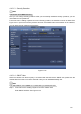
4.10.1.3 Security Question Note This function is for admin user only. Here you can change security questions. After you successfully answered security questions, you can reset admin account password. From main menu->Setting->System->Account->Security question, the interface is shown as below. See Figure 4-212. Input correct security answers and then click Delete button at the bottom of the interface, you can reset security questions and answers. Figure 4-212 4.10.1.
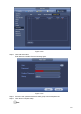
Figure 4-213 Step 2 Click Add User button. Enter Add User interface. See the following figure. Figure 4-214 Step 3 Step 4 Set user name, password and then select group from the dropdown list. Click Save to complete setup.
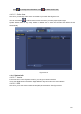
Click to change user information, click to delete current user. 4.10.1.5 Online User Here is for you manage online users connected to your NVR. See Figure 4-215. You can click button to disconnect or block one user if you have proper system right. System detects there is any newly added or deleted user in each five seconds and refresh the list automatically. Figure 4-215 4.10.2 System Info 4.10.2.1 Version From main menu->Info->System->version, you can go to version interface.
Figure 4-216 4.10.2.3 Event Information 4.10.2.3.1 Alarm Status From main menu->info-Event, here you can view the channel status of the remote device, connection log and etc. See Figure 4-217.
4.10.2.3.2 People Counting This function allows system to detect the people flow amount in the specified zone and display the people amount statistics image. From main menu->Info->Event->People Counting, you can go to the following interface. See Figure 4-218. Channel: Please select a channel from the dropdown list. Type: Please select report type from the dropdown list. It includes daily report/monthly report/annual report. You can click to select histogram or polygon chart.
Figure 4-219 4.10.3 Voice The audio function is to manage audio files and set schedule play function. It is to realize audio broadcast activation function. Note This function is for some series product only. 4.10.3.1 File Manage Here you can add audio file, listen to the audio file, or rename/delete audio file. Here you can also set audio volume. See Figure 4-220.
Figure 4-220 Click Add button, you can add audio file and import the audio file via the USB device. The audio file format shall be MP3 or PCM. See Figure 4-221. Note The file size shall be 2K-10MB. Figure 4-221 4.10.3.
It is to set schedule broadcast function. You can play the different audio files in the specified periods. See Figure 4-222. Figure 4-222 4.10.4 RS232 After setting RS232 parameters, the NVR can use the COM port to connect to other device to debug and operate. From Main menu->Setting->System->RS232, RS232 interface is shown as below. There are five items. See Figure 4-223. Function: There are various devices for you to select.
Baud rate:115200 Data bit:8 Stop bit:1 Parity: None After completing all the setups please click save button, system goes back to the previous menu. Figure 4-223 4.10.5 Broadcast It is to broadcast to the camera, or broadcast to a channel group. Step 1 From Mani menu->Setting->System->Broadcast. Enter the following interface. See Figure 4-224.
Figure 4-224 Step 2 Click Add group. Enter add group interface. See Figure 4-225. Figure 4-225 Step 3 Input group name and select one or more channels.
Step 4 Click Save button to complete broadcast group setup. Note On the broadcast interface, click to change group setup, click After complete broadcast setup, on the preview interface and then click to delete group. on the navigation bar, device pops up broadcast diaologue box. Select a group name and then click begin broadcast. See Figure 4-226. to Figure 4-226 4.10.6 Security 4.10.6.1 IP Filter IP filter interface is shown as in Figure 4-227. You can add IP in the following list.
and then current item is not in the list. b) System max supports 64 items. c) Address column supports IPv4 or IPv6 format. If it is IPv6 address, system can optimize it. For example, system can optimize aa:0000: 00: 00aa: 00aa: 00aa: 00aa: 00aa as aa:: aa: aa: aa: aa: aa: aa. d) System automatically removes space if there is any space before or after the newly added IP address. e) System only checks start address if you add IP address.
Figure 4-228 4.10.6.2 System Service The device supports to enable and disable various system internal services. Step 1 From main menu->System->Security ->System Service. The System Service interface is displayed. See Figure 4-229. Step 2 Figure 4-229 Configure the parameters. For details, see the below table. Parameter Description Password Reset Enabled by default. If it is disabled, the user can only use the security questions to reset the password. Mobile Phone Push Enabled by default.
Parameter Description The device can be connected via this protocol when enabled. Audio/VideoEncryption Step 3 The stream transmission is encrypted when this function is enabled.The associated device or software shall support decryption. Click OK to complete the configuration. 4.10.7 Auto Maintain Here you can set auto-reboot time and auto-delete old files setup. You can set to delete the files for the specified days. See Figure 4-230. You can select proper setup from dropdown list.
Figure 4-231 c) Select backup device and then set channel, file start time and end time. d) Click add button, system begins search. All matched files are listed below. System automatically calculates the capacity needed and remained. See Figure 4-232. e) System only backup files with a √ before channel name. You can use Fn or cancel button to delete √ after file serial number. f) Click backup button, you can backup selected files. There is a process bar for you reference.
h) Click backup button, system begins burning. At the same time, the backup button becomes stop button. You can view the remaining time and process bar at the left bottom. Note During backup process, you can click ESC to exit current interface for other operation (For some series product only). The system will not terminate backup process. The file name format usually is: Channel number+Record type+Time. In the file name, the YDM format is Y+M+D+H+M+S. File extension name is .dav. 4.10.8.
Note System cannot open config backup interface again if there is backup operation in the process. System refreshes device when you go to the config backup every time and set current directory as the root directory of the peripheral device. If you go to the configuration backup interface first and then insert the peripheral device, please click Refresh button to see the newly added device. 4.10.8.3 Backup Log a) From Main menu->Info->Log, the interface is shown as below. See Figure 4-234.
Figure 4-235 4.10.9 Default Warning! After you use default function, some your customized setup may lose forever! Please think twice before you begin the operation! You can restore factory default setup to fix some problems when the device is running slowly. Configuration error occurred. From Main menu->Setting->System->Default, you can go to the default interface. See Figure 4-236. Check an item you want to restore default setup, or check the All to select all items.
Figure 4-236 4.10.10 Upgrade 4.10.10.1 File Update From Mani menu->Setting->Info->Update, you can go to the following interface. See Figure 4-237. Step 1 Insert USB device that contain the upgrade file. Step 2 Click Start button and then select the .bin file. Step 3 You can see the corresponding dialogue box after the update process is complete.
Figure 4-237 4.10.10.2 Online Upgrade When the NVR is online, you can use the online upgrade to update the firmware. Before the online upgrade, system needs to detect if any new version is available. It includes auto check and manual check. Auto check: System automatically detects if any new version is available once in a while. Manual check: Detect new version at real time. During the upgrade process, make sure that the network connection and power supply are normal.
Figure 4-238 Step 2 Version check. Auto check: Select the Auto check for updates check box and click Save. Note System enables this function by default. Manual check: Click Manual Check. System starts to search new version and displays the result after the check is completed. When system displays that it is the latest version, the current version is the latest one and you do not need to upgrade it.
From Mani menu->Operation->Shutdown, you can see an interface shown as in Figure 4-239. Shutdown: System shuts down and turns off power. Logout: Log out menu. You need to input password when you login the next time. Restart: reboot device. If you shut down the device, there is a process bar for your reference, system waits for 3 seconds and then shut down (You cannot cancel). Please note, sometimes you need to input the proper password to shut down the device.
5 Web Operation 5.1 General Introduction If it is your first time to login the device, please initialize your device first. Refer to chapter 5.2 Device Initialization for detailed information. The device web provides channel monitor menu tree, search, alarm setup, system setup, PTZ control and monitor window and etc. Note Slight difference may be found on user interface. Please refer to the actual product for detailed information. Device supports various browsers such as Safari, Chrome and etc.
Figure 5-1 Step 3 Set login password of admin. User name: The default user name is admin. Password/confirm password: The password ranges from 8 to 32 digitals. It can contain letters, numbers and special characters (excluding “'”,“"”,“;”,“:”,“&”) . The password shall contain at least two categories. Usually we recommend the strong password. WARNING Step 4 STRONG PASSWORD RECOMMENDED-For your device own safety, please create a strong password of your own choosing.
Figure 5-2 Step 5 Set security questions. Note After setting the security questions here, you can use the email you input here or answer the security questions to reset admin password Refer to chapter 5.4 Reset password for detailed information. Cancel the email or security questions box and then click Next button to skip this step. Email: Input an email address for reset password purpose. Scan the QR code to reset the password, you need to receive the security code by the email.
Figure 5-3 5.3 Log in Open the IE and then input the NVR IP address in the address column. For example, if your NVR IP address is 192.168.1.108, then please input http:// 192.168.1.108 in IE address column. See Figure 5-4. Input IP address here. Figure 5-4 System pops up warning information to ask you whether install Web plug-in or not. Please click yes button. After installation, the interface is shown as below. See Figure 5-5.
Figure 5-5 Please input your user name and password. Factory default user name is admin and password is what you set in chapter 5.2 Device initialization. 5.4 Reset Password If you forgot admin password, you can reset the password by email or by answering the security questions (local menu only). When the password reset function is enabled, you can scan the QR code on the Web to reset the password.
Figure 5-6 Step 3 Click OK. System enters the following interface. See Figure 5-7. Note After clicking OK, we will collect your personal information such as cell phone number, MAC address and device serial number. The collected information is used for verifying device legality and sending security code. Please read the notice carefully and confirm if you agree with the collection or not.
Figure 5-7 Step 4 Follow the prompts on the interface and then scan the QR code to get the security code. WARNING Step 5 Step 6 For the same QR code, max scan twice to get two security codes. Refresh the QR code if you want to get security code again. The security code on you email is only valid for 24 hours. After five times security code failure, the admin account will be locked for 5 minutes. Input the security code on the email and then click Next button. Input new password and then confirm.
Figure 5-8 Section 3: Open all. Open all button is to enable/disable all-channel real-time monitor. Here you can select main stream/sub stream too. See Figure 5-9. Figure 5-9 Section 4: Start Talk button. You can click this button to enable audio talk. Click 【▼】 to select bidirectional talk mode. There are four options: DEFAULT, G711a, G711u and PCM. See Figure 5-10. After you enable the bidirectional talk, the Start talk button becomes End Talk button and it becomes yellow.
Figure 5-12 Section 7: Zero-channel encoding. Please refer to chapter 5.9 for detailed information. Section 8: PTZ operation panel. Please refer to chapter 5.7 for detailed information. Section 9: Image setup and alarm setup. Please refer to chapter 5.8 for detailed information. Section 10: From the left to the right ,you can see video quality/fluency/ full screen/1-window/4-window/6-window/8-window/9-window/13-window/16-window/20-window/25-win dow/36-window..
Figure 5-14 On the top right corner, there are six unction buttons. See Figure 5-15. 1 2 3 4 5 Figure 5-15 1: Digital zoom: Click this button and then left drag the mouse in the zone to zoom in. right click mouse system restores original status. 2: Local record. When you click local record button, the system begins recording and this button becomes highlighted. You can go to system folder RecordDownload to view the recorded file. 3: Snapshot picture. You can snapshot important video.
Parameter Function Tour Select Tour from the dropdown list. Input preset value in the column. Click Add preset button, you have added one preset in the tour. Repeat the above procedures you can add more presets in one tour. Or you can click delete preset button to remove one preset from the tour. Pattern Select Pattern from the dropdown list. You can input pattern value and then click Start button to begin PTZ movement such as zoom, focus, iris, direction and etc.
Select one monitor channel video and then click Image button in section 9, the interface is shown as Figure 5-17. 5.8.1 Image Here you can adjust its brightness, contrast, hue and saturation. (Current channel border becomes green). Or you can click Reset button to restore system default setup. Figure 5-17 5.8.2 Alarm output Here you can enable or disable the alarm signal of the corresponding port. See Figure 5-18. Figure 5-18 5.
Figure 5-19 5.10 WAN Login In WAN mode, after you logged in, the interface is shown as below. See Figure 5-20. Figure 5-20 Please refer to the following contents for LAN and WAN login difference. 1) In the WAN mode, system opens the main stream of the first channel to monitor by default. The open/close button on the left pane is null. 2) You can select different channels and different monitor modes at the bottom of the interface.
Figure 5-21. Figure 5-21 Important The window display mode and the channel number are by default. For example, for the 16-channel, the max window split mode is 16. 3) Multiple-channel monitor, system adopts extra stream to monitor by default. Double click one channel, system switches to single channel and system uses main stream to monitor. You can view there are two icons at the left top corner of the channel number for you reference. M stands for main stream. S stands for sub stream (extra stream).
Figure 5-22 Please refer to the following sheet for parameter information. Parameter Function Select IP address or the MAC address from the dropdown list and then input the corresponding information, click Search button to view the results. Search Click Search button, you can view the searched device information on the list. It includes device IP address, port, device name, manufacturer and type. Uninitialized Click to search the initialized devices.
Parameter Function Type There are two connection types. You can use the network to connect to the camera or use the Wi-Fi. The means current network camera connection mode is general; the means current network camera mode is hotspot. Delete Select a device in the Added device list and then click Delete button, system can disconnect the device and remove it from the Added device list. Manual Add Click it, the interface is shown as in Figure 5-23. Here you can add network camera manually.
Parameter Function IP address Input remote device IP address. Input RTSP port of the remote device. The default setup is 554. RTSP port Note Skip this item if the manufacture is private or customize. Input HTTP port of the remote device. The default setup is 80. HTTP port Note Skip this item if the manufacture is private or customize. TCP port Input TCP port of the remote device. The default setup is 37777. User name/password The user name and password to login the remote device.
can see the following interface. See Figure 5-24 Please refer to the following sheet for log parameter information. Parameter Function DHCP Check the box here, system can auto allocate the IP address. The IP address, subnet mask, default gateway are reference only. Static Check the box here, you can set IP address, subnet mask, default gateway manually. IP address/subnet mask/default gateway You can input corresponding information here. User name/password The account you login the remote device.
Figure 5-24 Export IP System supports to export the registered device list and save it in the USB device. Step 1 Inset the USB device and click Export. The File Backup Encryption interface is displayed. See Figure 5-25. Figure 5-25 Step 2 File backup encryption is enabled by default. Click OK to select the save path. Step 3 Click Save. After the export is completed, system pops up a dialogue box to show that backup is completed. Note Backup encryption is enabled by default when exporting IP.
address, port, remote channel number, manufacturer, username and password. If file backup encryption is enabled, the extension name of the exported file is .backup. Except the NVR device, any other software cannot open and edit the file. If the backup encryption is disabled, the extension name of the exported file is .csv. It might lead to data leakage. Import IP You can import the added device list to add the device conveniently. Click Import button, and then select the import file.
Note Slight difference may be found since the connected network camera may not be same model. Here you can view device property information. The setups become valid immediately after you set. See Figure 5-27. Figure 5-27 Please refer to the following sheet for detailed information. Parameter Function Channel Please select a channel from the dropdown list. Period It divides one day (24 hours) to two periods. You can set different hue, brightness, and contrast for different periods.
Saturation It is to adjust monitor window saturation. The value ranges from 0 to 100. The default value is 50. The larger the number is, the strong the color is. This value has no effect on the general brightness of the whole video. The video color may become too strong if the value is too high. For the grey part of the video, the distortion may occur if the white balance is not accurate. Please note the video may not be attractive if the value is too low. The recommended value ranges from 40 to 60.
mode. Day/Night Customized: You can set the gain of the red/blue channel. The value reneges from 0 to 100. It is to set device color and the B/W mode switch. The default setup is auto. Color: Device outputs the color video. Auto: Device auto select to output the color or the B/W video according to the device feature (The general bright of the video or there is IR light or not.) B/W: The device outputs the black and white video.
you to set different frame rates for motion detection record and alarm record. Compression Smart Codec Video encode mode. H.264: Main Profile encode mode. H.264H: High Profile encode mode. H.264B: Baseline Profile encode mode. H.265: Main Profile encode mode. MJPEG: System needs high bit streams to guarantee video definition. Use the recommended max bit stream value to get the better video effect. This function is to reduce bit streams.
Video/audio You can enable or disable the video/audio. The main stream is enabled by default. After enable the audio function, the record file is composite file consisting of the video and audio. For the sub stream 1, please enable video first and then enable audio function. Audio format Set audio encode format. Note Different series products support different audio encode mode. Please refer to the actual interface for detailed information.
Figure 5-30 Please refer to the following sheet for detailed information. Parameter Function Cover-area Check Preview or Monitor first. Click Set button, you can privacy mask the specified video in the preview or monitor video. System max supports 4 privacy mask zones. You can enable this function so that system overlays time information in video window. You can use the mouse to drag the time title position. You can view time title on the live video of the WEB or the playback video.
Figure 5-31 5.11.1.4 Channel Name Here you can set channel name. See Figure 5-32. Figure 5-32 5.11.2 Network 5.11.2.1 TCP/IP The TCP/IP interface is shown as in Figure 5-33.
Figure 5-33 Please refer to the following sheet for detailed information. Parameter Function Mode There are two modes: static mode and the DHCP mode. The IP/submask/gateway are null when you select the DHCP mode to auto search the IP. If you select the static mode, you need to set the IP/submask/gateway manually. If you select the DHCP mode, you can view the IP/submask/gateway from the DHCP. If you switch from the DHCP mode to the static mode, you need to reset the IP parameters.
5.11.2.2 Port The connection interface is shown as in Figure 5-34. Figure 5-34 Please refer to the following sheet for detailed information. Parameter Function Max connection The max client login amount (such as WEB, platform, cellphone and etc). The value ranges from 1 to 128(default). TCP port The default value is 37777. You can input the actual port number if necessary. UDP port The default value is 37778. You can input the actual port number if necessary. HTTP port The default value is 80.
Figure 5-35 Please refer to the following sheet for detailed information. Parameter Function 2.4GHz Select the check box to enable Wi-Fi. SSID It is to set SSID name. You can use this name to search the device. Encryption Type Select the encryption type from the dropdown list, including WPA2 PSK, WPA PSK and OPEN. Password It is to set SSID password. You can use this password to connect to the network. Channel Select the channel to connect the Wi-Fi IPC. Gain Adjust the Wi-Fi signal intensity.
Subnet Mask Default Gateway NVR Wi-Fi AP. The IP address and default gateway shall be in the same network segment. Start IP/End IP Input start IP and end IP of DHCP server. The NVR device can allocate the IP address in the range you specified here. Upgrade Click it to upgrade Wi-Fi AP module. 5.11.2.4 Wi-Fi Please note this function is for the device of Wi-Fi module. The Wi-Fi interface is shown as in Figure 5-37.
Figure 5-38 Please refer to the following sheet for detailed information. Parameter Function WLAN type Here you can select 3G network type to distinguish the 3G module from different ISP. The types include WCDMA, CDMA1x and etc. APN/Dial No. Here is the important parameter of PPP. Authorization It includes PAP,CHAP,NO_AUTH. Pulse interval It is to set time to end 3G connection after you close extra stream monitor.
Figure 5-39 5.11.2.6 PPPoE The PPPoE interface is shown as in Figure 5-40. Input the PPPoE user name and password you get from the IPS (internet service provider) and enable PPPoE function. Please save current setup and then reboot the device to get the setup activated. Device connects to the internet via PPPoE after reboot. You can get the IP address in the WAN from the IP address column. Please note, you need to use previous IP address in the LAN to login the device.
Preparation Before the operation, check the DDNS type that the device supports. If the DDNS type is Quick DDNS. You do not need to register the domain name. If the DDNS is some other type, log in the website of the DDNS provider and register information like domain name. After you register the device and log in the DDNS website, you can view all connected device information of the current user. Step 1 Enter from main memu > Setup > Network > DDNS. DDNS setup interface is shown as in Figure 5-41.
Parameter Description Password The password you input to log in the server. Test After the configuration, click Test and system saves the configuration and check if the domain name can be registered successfully. If succeeded, go to step4. If failed, check if the domain information is correct and clear the browser buffer. System supports this function when DDNS type is NO-IP DDNS. Update period The time interval to send update request. Unit: Minute. Step 4 Click Save to complete the setting.
Parameter Function password and the sender information. User Name The user name of the sender email account. Password The password of sender email account. Sender Sender email address. Authentication (Encryption mode) You can select SSL or none. Subject Input email subject here. Attachment System can send out the email of the snapshot picture once you check the box here. Receiver Input receiver email address here. Max three addresses. It supports SSL, TLS email box.
Figure 5-43 Please refer to the following sheet for detailed information. Parameter Function PAT Check the corresponding box to enable PAT function. Status Display UPnP function status. Port mapping list It is corresponding to the UPnP mapping information on the router. Check the box before the service name to enable current PAT service. Otherwise, the service is null. Service name: Customized name. Protocol: Protocol type. Internal port: The port mapped to the port.
Figure 5-44 Please refer to the following sheet for detailed information. Parameter Function Version Select by clicking the check box in front of the corresponding version. System selects V3 by default. There might be some risks for V1 and V2. SNMP Port The listening port of the proxy program of the device. It is a UDP port not a TCP port. The value ranges from 1 to 65535. The default value is 161 Read Community It is a string. It is a command between the manage process and the proxy process.
Parameter Trap address Trap port Read-only user Authentication mode Read-write user Password Encryption Type Function write. The destination address of the Trap information from the proxy program of the device. The destination port of the Trap information from the proxy program of the device. It is for the gateway device and the client-end PC in the LAN to exchange the information. It is a non-protocol connection port. It has no effect on the network applications. It is a UDP port not TCP port.
Figure 5-46 5.11.2.13 Alarm Centre The alarm center interface is shown as below. See Figure 5-47. This interface is reserved for you to develop. System can upload alarm signal to the alarm center when local alarm occurs. Before you use alarm center, please set server IP, port and etc. When an alarm occurs, system can send out data as the protocol defined, so the client-end can get the data. Figure 5-47 5.11.2.14 HTTPS In this interface, you can set to make sure the PC can successfully login via the HTTPS.
Figure 5-48 5.11.2.14.1 Create Server Certificate If it is your first time to use this function, please follow the steps listed below. In Figure 5-48, click button, input country name, state name and etc. Click Create button. See Figure 5-49. Note Please make sure the IP or domain information is the same as your device IP or domain name. Figure 5-49 You can see the corresponding prompt. See Figure 5-50. Now the server certificate is successfully created. Figure 5-50 5.11.2.14.
Figure 5-51 Click Open button, you can go to the following interface. See Figure 5-52. Figure 5-52 Click Install certificate button, you can go to certificate wizard. See Figure 5-53.
Figure 5-53 Click Next button to continue. Now you can select a location for the certificate. See Figure 5-54. Figure 5-54 Click Next button, you can see the certificate import process is complete. See Figure 5-55.
Figure 5-55 Click Finish button, you can see system pops up a security warning dialogue box. See Figure 5-56. Figure 5-56 Click Yes button, system pops up the following dialogue box, you can see the certificate download is complete. See Figure 5-57. Figure 5-57 5.11.2.14.3 View and set HTTPS port From Setup->Network->Port, you can see the following interface. See Figure 5-58. You can see HTTPS default value is 443.
Figure 5-58 5.11.2.14.4 Login Open the browser and then input https://xx.xx.xx.xx:port. xx.xx.xx.xx: is your device IP or domain mane. Port is your HTTPS port. If you are using default HTTPS value 443, you do not need to add port information here. You can input https://xx.xx.xx.xx to access. Now you can see the login interface if your setup is right. 5.11.2.15 P2P You can use your cell phone to scan the QR code and add it to the cell phone client.
Check the Enable box to enable P2P function and then click the Save button. When the Status shows Online, the P2P registration is successful. P2P is enabled by default. To enable you to manage the device on the mobile APP, we will collect device information like IP address, MAC address, device name and device SN. The collected information is only used for remote device access. 5.11.3 Event 5.11.3.1 Video detect 5.11.3.1.
Figure 5-61 Figure 5-62 Figure 5-63 274
Figure 5-64 Figure 5-65 Please refer to the following sheet for detailed information. Parameter Function Enable You need to check the box to enable motion detection function. Please select a channel from the dropdown list. Period Motion detection function becomes activated in the specified periods. See Figure 5-61. There are six periods in one day. Please draw a circle to enable corresponding period. Click OK button, system goes back to motion detection interface, please click save button to exit.
Parameter Function setup. If you click ESC button to exit the region setup interface system will not save your zone setup. Record channel System auto activates motion detection channel(s) to record once an alarm occurs. Please note you need to set motion detect record period and go to Storage-> Schedule to set current channel as schedule record. Record Delay System can delay the record for specified time after alarm ended. The value ranges from 10s to 300s. Alarm out Enable alarm activation function.
Figure 5-66 5.11.3.1.3 Tampering The tampering interface is shown as in Figure 5-67. After analysis video, system can generate a tampering alarm when the detected moving signal reached the sensitivity you set here. For detailed setups, please refer to chapter 5.11.3.1.1 motion detect for detailed information. Figure 5-67 5.11.3.1.4 Scene Change From main window->Setup->Event->Video detect->Scene change, the video diagnosis interface is shown as in Figure 5-68.
Figure 5-68 For detailed setups, please refer to chapter 5.11.3.1.1 motion detect for detailed information. 5.11.3.2 IVS Plan The smart plan is for the smart network camera. If you do not set a rule here, you cannot use the intelligent functions in IVS (Chapter 5.11.3.3), Face detection (Chapter 5.11.3.4) and People counting (Chapter 5.11.3.5) when you are connecting to a smart network camera. There are two types to realize intelligent analytics function.
Select a channel from the dropdown list. Click Add button, you can see an interface shown as below. See Figure 5-70. Select a channel from the dropdown list and then set preset. Click Add button and then set the corresponding rule. Note Some smart camera does not need to add the preset. Please refer to the actual product for detailed information. Figure 5-70 Click OK button to complete the setup.
the video height and width. The recommended height is 10% of the video. The object and the background brightness different shall be more than 10 grey levels. The object shall remain on the video for more than 2 seconds. The moving distance is larger than its own width and shall not be smaller than 15pixels (CIF resolution). The surveillance environment shall not be too complicated. The IVS function is not suitable for the environment of too many objects or the changing light.
Then you can set corresponding parameters. Click OK button to complete the setup. 5.11.3.3.2 Tripwire From main menu->Setup->Event-> Behavior analytics->Behavior analytics, click you can see the following interface. See Figure 5-73. System generates an alarm once there is any object crossing the tripwire in the specified direction. Figure 5-73 Check the Tripwire box to enable tripwire function. Select SN (Line1/2/3/4) and direction, and then input customized rule name.
Figure 5-74 Click to draw filter object. See Figure 5-75. Figure 5-75 Select the blue line and then use mouse to adjust zone size. Note Each rule can set two sizes (min size/max size). Once the object is smaller than the min size or larger than the max size, there is no alarm. Please make sure the max size is larger than the min size. Click Ok to complete the rule setup.
For detailed setups, please refer to chapter 5.11.3.1.1 motion detect for detailed information. 5.11.3.3.3 Intrusion (Cross warning zone) From main menu->Setup->Event-> Behavior analytics->Behavior analytics, click , and then select rule type as intrusion, you can see the following interface. See Figure 4-126. Note: System supports customized area shape and amount. Support enter/leave/both detection.
Figure 5-77 For detailed setups, please refer to chapter 5.11.3.1.1 motion detect for detailed information. 5.11.3.3.4 Abandoned Object Detect From main menu->Setup->Event-> Behavior analytics->Behavior analytics, click , and then select rule type as abandoned object detection, you can see the following interface. See Figure 5-78. System supports customized area shape and amount. Support duration setup. Support objects filter function.
Figure 5-78 Check the Object box to enable object detect function. Period: System can generate an alarm once the object is in the zone for the specified period. Click to draw the rule. See Figure 5-79. Figure 5-79 Now you can draw a rule. Left click mouse to draw a line, until you draw a rectangle, you can right click mouse. Click Ok to complete the rule setup.
For detailed setups, please refer to chapter 5.11.3.1.1 motion detect for detailed information. 5.11.3.3.5 Missing Object Detect From main menu->Setup->Event-> Behavior analytics->Behavior analytics, click , and then select rule type as missing object detection, you can see the following interface. See 错误!未找到引用源。. System supports customized area shape and amount. Support period setup. Support objects filter function. Figure 5-80 Click to draw the rule. See Figure 5-81.
Click Ok to complete the rule setup. For detailed setups, please refer to chapter 5.11.3.1.1 motion detect for detailed information. 5.11.3.3.6 Loitering From main menu->Setup->Event-> Behavior analytics->Behavior analytics, click , and then select rule type as loitering detection, you can see the following interface. See 错误!未找到引用源。. Note System supports customized area shape and amount. Support duration setup. Support objects filter function.
Figure 5-83 Duration: System can generate an alarm once the object is in the zone for the specified period. Sensitivity: It is to set alarm sensitivity. The value ranges from 1 to 10.The default setup is 5. Click to draw the rule. Click OK to complete the rule setup. For detailed setups, please refer to chapter 5.11.3.1.1 motion detect for detailed information. 5.11.3.3.
Figure 5-84 Click to draw the rule. Click OK to complete the rule setup. For detailed setups, please refer to chapter 5.11.3.1.1 motion detect for detailed information. 5.11.3.3.9 Global Config From main menu->Setup->Event->Behavior analytics->Global, you can go to the global configuration interface. See the below figure. Channel: Please select a channel from the dropdown list. Preset: Select a preset you want to set the rule.
Figure 5-85 5.11.3.4 Face Detect (Optional) When camera detects human face, system can generate an alarm. From main menu->Setup->Event->Face detect, the interface is shown as in Figure 5-86. Enable face boost: Check the box here, system can enhance the human face display pane. Sensitivity: System supports 6 levels. The sixth level has the highest sensitivity. Figure 5-86 For detailed setups, please refer to chapter 5.11.3.1.1. 5.11.3.
From main menu->Setup->Event->People counting, you can see an interface shown as the below figure. Channel: Please select a channel from the dropdown list. Check the box to enable people counting function. OSD overlay: Check the box here; you can view the people amount on the surveillance video. Direction: It is to set people flow direction. It includes entry/exit. Entry No.: It is to set people entry amount. System can generate an alarm once the amount has exceeded the threshold. Exit No.