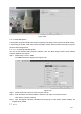
Figure 5-88 5.11.3.7 Plate Recognition License plate recognition adopts video image recognition technology to extract the license plate number in video image and match it with the pre-set license plate number. After successful matching, the system performs alarm linkage action 5.11.3.7.1 Configuring Plate Recognition You can set the different plate recognition detection rules and alarm linkage actions under different confitions (B/W list and regular) Step 1 Select Setup > Event > ANPR.
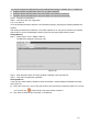
You need to configure the B/W list before using the B/W alarm linkage. For details, see 4.7.7.2 B/W List. Regular: System activates alarm when any car plate is detected. Blacklist: System activates alarm only when plates in the black list is detected. Whitelist: System activates alarm only when plates in the white list is detected. Step 5 Configure the parameters. Step 6 Click OK to save the configuration. 5.11.3.7.2 B/W List It is to set the blacklist and the whitelist.
Figure 5-91 Importing /Exporting B/W List System supports to import B/W list from the peripheral USB device and export B/W list to the USB device. System supports to import .csv files and .xlsx files, and the exported files are in the format of .csv or .backup. Importing B/W list: Click Import, select the file, and then click Open to import the file. Export B/W list: Click Export and the File Backup Encryption interface is displayed. See Figure 5-92. Enter the password and click OK.
Intensity change: Check the box here, system can generate an alarm once the audio volume becomes strong. Sensitivity: It refers to the audio recognition sensitivity. The higher the value is, the higher the sensitivity is. Threshold: It is to set intensity change threshold. The smaller the value is, the higher the sensitivity is. For detailed setups, please refer to chapter 5.11.3.1.1 motion detect for detailed information. Figure 5-93 5.11.3.
Figure 5-95 Figure 5-96 Please refer to the following sheet for detailed information. Parameter Function Enable You need to check the box to enable this function.
Parameter Function Please select a channel from the dropdown list. Period This function becomes activated in the specified periods. There are six periods in one day. Please draw a circle to enable corresponding period. Select date. If you do not select, current setup applies to today only. You can select all week column to apply to the whole week. Click OK button, system goes back to local alarm interface, please click save button to exit.
Figure 5-97 5.11.3.9.3 IPC external alarm The IPC external alarm interface is shown as in Figure 5-98. Network alarm refers to the alarm signal from the network. System does not anti-dither and sensor type setup. For setup information, please refer to chapter 5.11.3.9.1. Figure 5-98 5.11.3.9.
The IPC offline alarm interface is shown as in Figure 5-99. System can generate an alarm once the network camera is offline. For setup information, please refer to chapter 5.11.3.9.1. Figure 5-99 5.11.3.10 Abnormality From main menu->Setup->Event->Abnormality, it includes four types: HDD/Network/User/Device. See Figure 5-100 through Figure 5-103.
Figure 5-101 Figure 5-102 300
Figure 5-103 Please refer to the following sheet for detailed information. Parameter Function Event Type The abnormal events include: HDD: No disk, disk error, disk no space; Network: Net disconnection, IP conflict, MAC conflict. User: Illegal login. Device: Temperature is too high, fan speed is abnormal. Please note this function is for some series product only. You can set one or more items here. Less than: You can set the minimum percentage value here.
Parameter Function Alarm upload System can upload the alarm signal to the center (Including alarm center. Send Email If you enabled this function, System can send out an email to alert you when an alarm occurs. Buzzer Check the box here to enable this function. The buzzer beeps when an alarm occurs. Log Check the box here, system can record the network event alarm log. 5.11.3.11 Alarm Out The alarm output interface is shown as below.
Parameter Function HDD full It is to select working mode when hard disk is full. There are two options stop recording or rewrite. Stop: If current HDD is full while there is no idle HDD, then system stops recording, Overwrite: If the current HDD is full while there is no idle HDD, then system overwrites the previous files. Pack duration It is to specify record duration. The max value is 120 minutes. Auto delete old files Never: Do not auto delete old files.
Figure 5-107 Figure 5-108 Please refer to the following sheet for detailed information. Parameter Function Channel Please select a channel from the dropdown list. Pre-record Please input pre-record time here. The value ranges from 0 to 30. Redundancy Check the box here to enable redundancy function. Please note this function is null if there is only one HDD. Snapshot Check the box here to enable snapshot function. Holiday Check the box here to enable holiday function.
Parameter Function bottom of the interface, current setup is for today only. Please click Save button and then exit. Copy Copy function allows you to copy one channel setup to another. After setting in channel, click Copy button, you can go to interface Figure 5-108. You can see current channel name is grey such as channel 1. Now you can select the channel you want to paste such as channel 5/6/7. If you want to save current setup of channel 1 to all channels, you can click the first box “ALL”.
Figure 5-111 FTP transmits data with clear text mode and SFTP transmits data with encrypted mode. SFTP is recommended. Host IP: The host IP you have installed the FTP server. Port: The default SFTP port number is 22 and the default FTP port number is 21. User name/Password: The account for you to access the FTP server. Remote directory: The folder you created under the root path of the FTP according to the corresponding rule.
Week day/Period: Please select from the dropdown list and for each day, you can set two periods. Type: Please select uploaded record type (Alarm/intelligent/motion detect/regular). Please check the box to select upload type. 5.11.4.4 Record Control The interface is shown as in Figure 5-112. Figure 5-112 Please refer to the following sheet for detailed information. Parameter Function Channel Here you can view channel number. The number displayed here is the max channel amount of your device.
Stop Stop current channel record no matter what period applied in the record setup. Start all/ stop all Check the corresponding All button, you can enable or disable all channels record. 5.11.4.5 RAID Manager Important Please make sure your purchased product support the RAID function, otherwise you cannot see the following interface.
Note Click to delete RAID. Figure 5-113 5.11.4.5.2 Hotspare disks In Figure 5-113, click hotspare button, you can add the hot spare HDD. See Figure 5-114. The type includes two options: Global: It is global hotspare disk. When any RAID becomes degrading, it can replace and build the RAID. Local: It is local hotspare disk. When the specified RAID becomes degrading, it can replace and build the RAID. Select a hot spare device and then click Delete button. Click Apply button to delete.
5.11.4.6 Storage 5.11.4.6.1 Main Stream The main stream interface is shown as in Figure 5-115. Here you can set corresponding HDD group to save main stream. Figure 5-115 5.11.4.6.2 Sub Stream The sub stream interface is shown as in Figure 5-116. Here you can set corresponding HDD group to save sub stream. Figure 5-116 5.11.4.6.3 Snapshot The snapshot interface is shown as in Figure 5-117. Here you can set corresponding HDD group to save snapshot picture.
Figure 5-117 5.11.5 Setting 5.11.5.1 General The general interface includes general, date/time and holiday setup. 5.11.5.1.1 General The general interface is shown as in Figure 5-118. Figure 5-118 Please refer to the following sheet for detailed information. Parameter Function Device ID It is to set device name. Device No. It is device channel number. Language You can select the language from the dropdown list. Please note the device needs to reboot to get the modification activated.
Video Standard This is to display video standard such as PAL. Auto logout Here is for you to set auto logout interval once login user remains inactive for a specified time. Value ranges from 0 to 60 minutes. IPC Time Sync You can input an interval here to synchronize the NVR time and IPC time. Navigation bar Check the box here, system displays the navigation bar on the interface. 5.11.5.1.
DST Here you can set day night save time begin time and end time. You can set according to the date format or according to the week format. NTP You can check the box to enable NTP function. NTP server You can set the time server address. Port It is to set the time server port. Interval It is to set the sync periods between the device and the time server. 5.11.5.1.3 Holiday Setup Holiday setup interface is shown as in Figure 5-120.
Figure 5-121 Please refer to the following sheet for detailed information. Parameter Function Resolution There are four options: 1920×1080, 1280×1024(default), 1280×720, 1024×768. Please note the system needs to reboot to activate current setup. Color mode Please select from the dropdown list. Transparency Here is for you to adjust transparency. The value ranges from 128 to 255. Time title/channel title Check the box here, you can view system time and channel number on the monitor video.
needs to input user name and password to login again. Display intelligent rule(s) Check the box to enable IVS function, system can display IVS rule on the preview interface. 5.11.5.2.2 Tour The tour interface is shown as in Figure 5-122. Here you can set tour interval, split mode, motion detect tour and alarm tour mode. Figure 5-122 Please refer to the following sheet for detailed information. Parameter Function Enable tour Check the box here to enable tour function.
Device max supports 5 customized videos. Figure 5-123 Click and then click to select basic mode In regular mode, drag the mouse in the preview frame, you can merge several small windows to one window so that you can get you desired split mode. After the setup, the selected window has the red frame. Select the merging window, the frame is red; you can click to cancel the merge to restore regular mode. Click OK to exit. 5.11.5.3 RS232 The RS232 interface is shown as in Figure 5-124.
Parameter Function Protocol Select the corresponding dome protocol. Default setup is console. Select the baud rate. Default setup is 115200. Baud Rate Data Bit The value ranges from 5 to 8. Default setup is 8. Stop bit There are two options: 1/2. Default setup is 1. Parity There are five options: none/odd/even/space/mark. Default setup is none. 5.11.5.4 PTZ The PTZ interface is shown as in Figure 5-125 (Local) and Figure 5-126 (Remote).
Figure 5-126 Please refer to the following sheet for detailed information. Parameter Function Channel Select speed dome connected channel. PTZ Type There are two options: local/remote. Please select remote type if you are connecting to the network PTZ. Please select local type if you are using RS485 to the PTZ camera. Protocol Select the corresponding dome protocol such as PELCOD. Address Set corresponding dome address. Default value is 1.
Figure 5-128 Check the box to enable POS function, Click Set button; you can see the following interface. See Figure 5-129. Figure 5-129 Set source IP and destination IP, and then click OK. System goes back to Figure 5-128. Source IP: POS device IP address. Destination IP: NVR IP address. In Figure 5-128, click Channel Set button, select the channel you want to overlay POS information. Click OK button to complete the setup. Tips : Click it to delete POS setup. : Click it to change setup information.
5.11.5.6.1 File List From main menu->Setup->System->Voice->File list, here you can add audio file, or delete audio file. See Figure 5-130. Figure 5-130 Click Add button, you can add audio file and import the audio file via the local computer. See Figure 5-131. Figure 5-131 5.11.5.6.2 Schedule It is to set schedule broadcast function. You can play the different audio files in the specified periods. From main menu->Setup->System->Voice->.Schedule, you can see the following interface. See Figure 5-132.
Figure 5-132 Please refer to the following sheet for detailed information. Parameter Function Period There are six periods. Check the box to enable current setup. Repeat It is to set audio file repeat times in the specified period. Interval It is the audio file repeated interval in the specified period. Output port There are two options: MIC (default)/audio. When reuse the MIC port and bidirectional talk port, the bidirectional port has the higher priority.
Add user It is to add a name to group and set the user rights. Step 1 Step 2 Click Add user button. Enter add user interface. See Figure 5-134. Here you can input the user name and password and then select one group for current user. Figure 5-134 Step 3 Click the Set button after the period. It is to set valid period to use current account. See Figure 5-135.
Figure 5-135 Step 4 Click Setting to set the periods. Or you can draw on the interface directly. There are six periods in one day. Or you can input start time and end time directly. Check the box before the date, the settings are for the selected date(s). Check the box before the period1-6, it is to enable the period function. Click Save to complete the setup. Note Please note the user rights shall not exceed the group right setup.
Figure 5-136 Note For admin, you can change the email information. See Figure 5-137.
Figure 5-137 Modify password It is to modify the user password. Step 1 In Modify user interface, click Modify password box. See Figure 5-138.
Step 2 Step 3 Figure 5-138 Input old password, and then input new password and confirm. Click Save button. Note The password ranges from 8 to 32 digitals. It can contain letters, numbers and special characters (excluding “'”,“"”,“;”,“:”,“&”) . The password shall contain at least two categories. Usually we recommend the strong password. WARNING STRONG PASSWORD RECOMMENDED-For your device own safety, please create a strong password of your own choosing.
Figure 5-139 Add group It is to add group and set its corresponding rights. Step 1 Click Add group button. Enter add group interface. See Figure 5-140. Figure 5-140 Step 2 Step 3 Input the group name and then check the box to select the corresponding rights. system, playback, and monitor. Click Save button. It includes: Modify group Step 1 Select a group and then click . See Figure 5-141.
Figure 5-141 Step 2 Change corresponding information and then click Save button. 5.11.5.7.3 ONVIF User When the camera from the third party is connected with the NVR via the ONVIF user, please use the verified ONVIF account to connect to the NVR. Step 1 From main menu->Setting->System->Account->ONVIF User. Enter ONVIF user interface. See the following figure. Figure 5-142 Step 2 Click Add user button. Enter add user interface. See Figure 5-143.
Figure 5-143 Step 3 Step 4 Set user name, password and then select group from the dropdown list. Click Save to complete setup. Note Click to change user information, click to delete current user. 5.11.5.8 Security To enhance device network security and protect device data, please set the access right of the IP host (IP host here refers to the IP PC or the server). After you enabled trusted sites function, only the IP listed below can access current NVR.
f) System may check newly added IP address exists or not. System does not add if input IP address does not exist. Delete: Click it to remove specified item. Edit: Click it to edit start address and end address. See Figure 5-145. System can check the IP address validity after the edit operation and implement IPv6 optimization. Default: Click it to restore default setup. In this case, the trusted sites and blocked sites are both null. Step 4 Click Save to complete setup.
Figure 5-146 5.11.5.10 Import/Export The interface is shown as in Figure 5-147. This interface is for you to export or import the configuration files. Figure 5-147 Please refer to the following sheet for detailed information. Parameter Function Browse Click to select import file. Import It is to import the local setup files to the system. Export It is to export the corresponding WEB setup to your local PC. 5.11.5.11 Default The default setup interface is shown as in Figure 5-148.
Figure 5-148 5.11.5.12 Upgrade CAUTION During the upgrade process, do not unplug the power cable, network cable, or shutdown the device. Improper upgrade program may result in device malfunction! There are two upgrade modes: file upgrade and online upgrade. 5.11.5.12.1 File Upgrade The upgrade interface is shown as in Figure 5-149. Please select the upgrade file and then click the update button to begin update. Please note the file name shall be as *.bin. Figure 5-149 5.11.5.12.
device name, firmware version and serial number. The collected information is used for verifying device legality and pushing upgrade notice. Click manual detection to view the latest new version on the cloud. If current version is the latest one, system prompts that “It is the latest version”. If there is new version available, system displays new version information such as release date and corresponding release note. Upgrade System Click Start to upgrade the system. 5.12 Information 5.12.
Figure 5-151 Please refer to the following sheet for log parameter information. Parameter Function Type Log types include: system operation, configuration operation, data operation, event operation, record operation, user management, log clear. Start time Set the start time of the requested log. End time Set the end time of the requested log. Search You can select log type from the drop down list and then click search button to view the list.
Figure 5-152 5.12.4 People Counting From main menu->Info->People counting, the interface is shown as in Figure 5-153. Figure 5-153 5.12.5 Heat Map From main menu->Info->Heat Map, the interface is shown as in Figure 5-154.
Figure 5-154 5.12.6 HDD From main menu->Info->HDD, the HDD interface is shown as in Figure 5-155. Here you can view HDD information. Figure 5-155 5.13 Playback Click Playback button, you can see an interface is shown as in Figure 5-156.
Figure 5-156 5.13.1 Search Record Please set record type, record date, window display mode and channel name. Select Date You can click the date on the right pane to select the date. The green highlighted date is system current date and the blue highlighted date means it has record files. Window Split Select window split mode. Click to display in full screen. Click ESC button to exit. See Figure 5-157. Figure 5-157 Select Channel 1~4 means main stream and A1~A4 means sub stream.
Figure 5-159 5.13.3 Playback Select a file you want to play and then click Play button, system can begin playback. You can select to playback in full-screen. Please note for one channel, system cannot playback and download at the same time. You can use the playback control bar to implement various operations such as play, pause, stop, slow play, fast play and etc. See Figure 5-160. Figure 5-160 5.13.
reference. Please go to you default file saved path to view the files. Figure 5-161 5.13.5 Load more It is for you to search record or picture. You can select record channel, record type and record time to download. Or you can use watermark function to verify file. 5.13.5.1 Download By File Select channel, record type, bit stream type and then input start time and end time. Click Search button, the download by file interface is shown as in Figure 5-162.
Click Download to local, system pops up the following interface for you to set record format and saved path. See Figure 5-163. Figure 5-163 You can click OK to download and view the download process. After the download operation, you can see corresponding dialog box. Download to USB Connect the corresponding p peripheral device, and then click Download to USB button, you can see the following interface. See Figure 5-164.
Figure 5-165 Set record format and saved path, you can click OK to download and view the download process. After the download operation, you can see corresponding dialog box. 5.13.5.3 Watermark Watermark interface is shown as In Figure 5-166. Please select a file and then click Verify button to see the file has been tampered with or not Figure 5-166 5.14 Smart Playback It is to search and playback the IVS file, human face file and plate recognition record.
There are two types to realize intelligent analytics function. Smart network camera supports intelligent functions: Some smart camera supports the intelligent functions. For NVR, it just displays the intelligent alarm information from the smart network camera and set or playback the record file. NVR supports intelligent functions: The connected network camera does not support intelligent video analytics function. The NVR supports the analytics function.
Select a file and then click , you can save current file to peripheral storage devices. Select a file and then click , you can lock current file in case it will be overwritten in the future Select a file and then click , you can mark the time of the detected event. 5.14.2 Plate Recognition It is to search and playback the record file containing the plate number. Step1 Select Smart Playback-> ANPR. The ANPR interface is displayd. See Figure 5-169.
Figure 5-170 Step4 Click the image and you can view the record file. Click Export Plate to export the plate information to local. Select a file and then click , you can save current file to peripheral storage devices. Select a file and then click , you can lock current file in case it will be overwritten in the future Select a file and then click , you can mark the time of the detected event. 5.14.3 Human Face System can search the record containing human face and then replay it.
The following human faces have been modified for privacy reason. The actually snapshot images have high definition. Figure 5-172 Step4 Click the image and you can view the record file. Select a file and then click , you can save current file to peripheral storage devices. Select a file and then click , you can lock current file in case it will be overwritten in the future Select a file and then click , you can mark the time of the detected event. 5.
Figure 5-173 Please refer to the following sheet for detailed information. Type Parameter Function Alarm Type Video loss System alarms when video loss occurs. Motion detection System alarms when motion detection alarm occurs. Tampering System alarms when camera is viciously masking. Disk full System alarms when disk is full. Disk error System alarms when disk error occurs. External alarm Alarm input device sends out alarm.
Figure 5-174 5.17 Un-install Web Control You can use web un-install tool “uninstall web.bat” to un-install web control.
6 Glossary DHCP: DHCP (Dynamic Host Configuration Protocol) is a network protocol. It is one of the TCP/IP protocol cluster. It is principally used to assign temporary IP addresses to computers on a network. DDNS: DDNS (Dynamic Domain Name Server) is a service that maps Internet domain names to IP addresses.
7 FAQ Questions Solutions NVR cannot boot up Input power is not correct. properly. Power connection is not correct. Power switch button is damaged. Program upgrade is wrong. HDD malfunction or something wrong with HDD ribbon. Seagate DB35.1, DB35.2, SV35 or Maxtor 17-g has compatibility problem. Please upgrade to the latest version to solve this problem. Front panel error. Main board is damaged. Input voltage is not stable or it is too low.
Questions Solutions NVR cannot control PTZ. Front panel PTZ error PTZ decoder setup, connection or installation is not correct. Cable connection is not correct. PTZ setup is not correct. PTZ decoder and NVR protocol is not compatible. PTZ decoder and NVR address is not compatible. When there are several decoders, please add 120 Ohm between the PTZ decoder A/B cables furthest end to delete the reverberation or impedance matching. Otherwise the PTZ control is not stable.
Questions Solutions Alarm setup is not correct. Alarm signal cannot been Alarm output has been open manually. disarmed. Input device error or connection is not correct. Some program versions may have this problem. Please upgrade your system. Alarm function is null. Alarm setup is not correct. Alarm cable connection is not correct. Alarm input signal is not correct. There are two loops connect to one alarm device. Camera quality is too low. Lens is dirty.
Questions I can not connect to the IPC Solutions Please make sure the IPC has booted up. IPC network connection is right and it is online IPC IP is in the blacklist. The device has connected to the too many IPC. It cannot transmit the video. Check the IPC port value and the time zone is the same as the NVR. After I set the NVR resolution as 1080P, my monitor can not display. Make sure current network environment is stable. Shut down the device and then reboot.
Otherwise it may result in HDD malfunction. Please make sure the device is away from the direct sunlight or other heating sources. Please keep the sound ventilation. Please check and maintain the device regularly.
8 Appendix A HDD Capacity Calculation Calculate total capacity needed by each device according to video recording (video recording type and video file storage time). Step 1: According to Formula (1) to calculate storage capacity qi that is the capacity of each channel needed for each hour, unit Mbyte.
9 Appendix B Compatible Network Camera List Please note all the models in the following list for reference only. For those products not included in the list, please contact your local retailer or technical supporting engineer for detailed information. Manufact ure Model Version Video Encode Audio/Vid eo Protocol AXIS P1346 5.40.9.2 H264 √ ONVIF/Private P3344/P3344E 5.40.9.2 H264 √ ONVIF/Private P5512 - H264 √ ONVIF/Private Q1604 5.40.3.2 H264 √ ONVIF/Private Q1604-E 5.40.
Manufact ure Model Version Video Encode Audio/Vid eo Protocol Cannon VB-M400 - H264 √ Private CNB MPix2.0DIR XNETM112011 1229 H264 √ ONVIF VIPBL1.3MIR VF XNETM210011 1229 H264 √ ONVIF IGC-2050F XNETM210011 1229 H264 √ ONVIF CP-NC9-K 6.E.2.7776 H264 √ ONVIF/Private CP-NC9W-K 6.E.2.
Manufact ure LG Imatek Panasonic PELCO Model Version Video Encode Audio/Vid eo Protocol HIDC-0100P h.2.2.1824 H264 √ ONVIF HIDC-1300V 2.0.0.21 H264 √ ONVIF HICC-1300W 2.0.1.7 H264 √ ONVIF HICC-2300 2.0.0.
Manufact ure Samsung Sony SANYO Model Version Video Encode Audio/Vid eo Protocol D5118 1.7.8.9310-A1. 5288 H264 √ Private IM10C10 1.6.13.9261-O2 .4657 H264 √ Private DD4N-X 01.02.0015 MPEG4 √ Private DD423-X 01.02.0006 MPEG4 √ Private D5220 1.8.3-FC2-2012 0614-1.9320-A 1.8035 H264 √ Private SNB-3000P 2.41 H264、MPEG4 √ ONVIF/Private SNP-3120 1.22_110120_1 H264、MPEG4 √ ONVIF/Private SNP-3370 1.21_110318 MPEG4 √ Private SNB-5000 2.
ZHEJIANG DAHUA VISION TECHNOLOGY CO.,LTD. Address:No.1199, Bin'an Road, Binjiang District, Hangzhou, P.R. China Postcode: 310053 Tel: +86-571-87688883 Fax: +86-571-87688815 Email:overseas@dahuatech.com Website: www.dahuasecurity.