Network Attached Storage User’s Manual V 1.0.
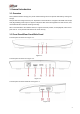
Table of Contents 1 2 General Introduction ............................................................................................................................4 1.1 Overview........................................................................................................................................4 1.2 Front Panel/Rear Panel/Side Panel ..........................................................................................4 1.3 Packing List .........................................
Welcome Thank you for purchasing our device! This user’s manual is designed to be a reference tool for your system. Please open the accessory bag to check. Contact your local retailer ASAP if something is missing or damaged in the bag.
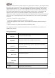
Important Safeguards and Warnings 1.Electrical safety All installation and operation here should conform to your local electrical safety codes. An apparatus with CLASS I construction shall be connected to a MAINS socket outlet with a protective earthing connection. Use a power supply which meets the requirements for SELV (Safety Extra Low Voltage) and complies with Limited Power Source according to IEC 60950-1. Refer to the device label for detailed information.
Note: This product has been tested and found to comply with the limits for a Class B digital device, pursuant to Part 15 of the FCC Rules. These limits are designed to provide reasonable protection against harmful interference in a residential installation. This product generates, uses, and can radiate radio frequency energy and, if not installed and used in accordance with the instructions, may cause harmful interference to radio communications.
1 General Introduction 1.1 Overview NAS (network attached storage) is a private network storage device for private data backup, sharing and storage. NAS provides the storage function (unit: TB) based on the Android OS. It supports 4K HDMI video output, HIFI (High-Fidelity) audio output. It supports cell phone APP remote management and data access, view, and downloads the record file and image remotely.
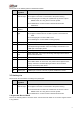
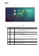
Please refer to the following table for detailed information. SN Indicator Function Light/Port 1 Power Power indicator light. indicator light The light is off if it has not connected to the power sourcing. The orange light is on during the system boot up process or press RESET button for a long time to reset the system. The white light is on when system is working properly after initialization. 2 Signal It is to receive the IR signal from the remote control.
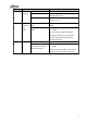
SN Name Contents 1 Whole Appearance There is any visible damage or not. package Package There is any accidental clash during transportation or not. Accessories Check all accessories are included in the bag or not. 2 Front The model on the front Check the model with the purchase panel and panel order. rear The label on the rear It is neat and clean or not. panel panel. Note Do not tear off, or discard the label.
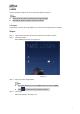
2 WEB Use PC (personal computer) to access the device WEB to manage it. Note Check the PC and device connection before login the WEB. Right now the browser supports Chrome and FireFox. 2.1 Login Use browser to access the device WEB, it is to access and manage the device remotely. Steps: Step 1 Step 2 Open browser and input the device IP address in the address column. Click Enter button. Enter WEB login interface. See Figure 2-1. Figure 2-1 Step 3 Enter user name and password.
Figure 2-2 Please refer to the following table for detailed information. SN Name Function 1 Main menu Click , enter main menu interface. See Figure 2-3. It is to view system applications and installed applications. 2 3 Task bar It is to display current running APP icon. Right click APP icon to restore, maximize, minimize, close the APP. Click Click to logout current user. Logout to select reboot or shut down. It is to reboot or shut down the device.
Figure 2-3 2.2 Photo It is to upload the photo to the device to storage and use the photo applications to play online. Steps: In the main interface, click , enter photo interface. See Figure 2-4. Right click Photo or click any photo in the list, it is to create a new photo or delete an old one. Select an album and then click Upload, or select photo(s) and then click open, it is to upload the image(s) on the local PC to the corresponding album.
Figure 2-4 2.3 Music It is to upload the video to the device to storage and use the player to play online. \ Steps: On the main interface, click , enter music interface. See Figure 2-5. Click Play all, device plays all songs in current list. Click Add song, and then select a music file to upload, click Open, it is to upload the local PC music file to the corresponding list. Input the search key words in corresponding search results.
Figure 2-5 Please refer to the following table for detailed information. Icon Function Click to play the previous song. Select a song in the list and then click the icon to play. Now the icon becomes ,click to pause paly. Click to switch to the next song. Click to change to lyric mode, it is to view the lyric. Click the icon again to go back to the list mode. Display current music play process, play time and total period. Click to add current music to the My favorites. Click to adjust volume.
Icon Function Click to view current play music list. Click Clear to clear play list. Display current played music amount. Click to view the played music list. 2.4 Video Upload the video file to the device to storage and use player to play online. Steps: In the main interface, click , enter audio/video interface. See Figure 2-6. Input key words in and click Enter button, device displays the corresponding search results. Move the mouse to the video file, device pops up .
Steps: In the main menu, click , enter file interface. See Figure 2-7. Right click the file name in the file list on the right pane, it is to download, copy/paste/cut, delete, rename the file, or view the file properties. Right click file, click download, it is to download the file to the local PC. Figure 2-7 Please refer to the following table for detailed information. Icon Function Click to go back to the previous path. Click to cancel go back to the previous path Click to refresh file list.
Icon Function Click to select file display mode. It includes list, small icon, medium icon and large icon. Click to select file sequence. It includes name, size, type and time modified. 2.6 Download System supports BT(BitTorrent), magnet-uri ,HTTP/HTTPS, FTP/FTPS to download file. It max supports 5 download tasks at the same time. Refer to appendix for Download Mode for BT(BitTorrent), magnet-uri ,HTTP/HTTPS, FTP/FTPS detailed information. Steps: In the main menu, click to enter download interface.
SN Function Download catalog bar. Downloading: Display downloading, pause, to be downloaded or error task information. 1 Finished: Display finished task information. Recycle: The deleted task information from the downloading list or the finished list. Task operation bar Click to add new download task. Refer to chapter 2.6.1 New task for detailed information. Pause task in the downloading list, click the icon or right click mouse and then select start to resume download process.
Enter download interface. See Figure 2-9. Step 2 Click . Enter Add task interface. Figure 2-9 Step 3 Input download link or add BT file. BT download: Add BT task and select corresponding .torrent file. Other download: Input download path. Different download modes have different download links. Please refer to the actual situation to set. Step 4 Select save path. Click to select path interface. See Figure 2-10. Click to select saved path.
Step 5 Click Download Now. Enter downloading list to view new task state and download process. 2.6.2 Delete Task Select a task in the list (download task, finished task or the task deleted in the recycle) and then click , or right click mouse and then select delete, enter delete interface. Note Check the box to select delete download file, system can delete the downloaded file at the same time. 2.6.3 Restore Task Go to the recycle to restore the download task.
Step 3 Select a task to be restored and then click , System restore the task. Go to the downloading interface to view the download task. Step 4 Click the of the corresponding download task. System begins downloading task again. 2.7 Surveillance Click , enter preview and monitor interface. See Figure 2-12. Connect to the camera, system can display real-time monitor video, playback record file, set camera parameters remotely.
using template to add. Here we introduce search and then add function. Search and then add: Search to find the remote device and then add. This function is useful if you do not know the remote device IP address. Add by IP address: Add remote device by IP address. This function is useful if you know the remote device IP address, user name and password. Batch add: Add several remote cameras by the same time. Please make sure these remote devices are in the same IP segment such as (192.168.1.1~192.
Figure 2-14 2. Click Found device. Enter search results interface. Note The remote device on the added list will not be displayed on the searched results. State column is to display current remote device has been initialized or not. means it has been initialized. See Figure 2-15. Figure 2-15 Please refer to the following table for detailed information. Icon/Item Function Filter the remote device via the IP address or the MAC address.
Icon/Item Function Check a device and then click the Modify button to change the remote device IP address. Modify Note Make sure the remote device is network camera and the manufacturer is private. Otherwise this function is null. Search Change remote device IP address one by one. Click to search remote device again. Name 3. Double click Function remote device or check the remote device and then click Add.
Name Function TCP port value. Default setup is 37777. Input the actual port number if necessary. TCP port Note Set TCP port value when manufacturer protocol is private. RTSP port value. Default setup is 554. Input the actual port number if necessary. RTSP port Note Do not need to set RTSP port value when manufacturer protocol is private or customized. Set the HTTP port value of the remote device. The default setup is 80.
Figure 2-17 2. Set IP range you want to add. Note The batch add is for the remote devices on the same IP segment. Please set the fourth field of the IP address. 3. 4. Refer to the above table to set other parameters. Click OK to complete the add process. Import template to add 1. Click to select save path and click Save to export template. The exported template file default name is RemoteConfig_2016-12-13.csv. 2016-12-13 refers to the exported date. 2.
Click or select a remote device and then click to delete a remote device. Click Refresh to refresh the remote device list. 2.7.1.2 Record Control The record includes auto record and manual record. After enable auto record function, the remote device can record at the specified period. Auto: Automatically record video of the specified record type at the specified period. Manual: Record for 24H. The record type is regular.
Name Function Refresh Click to get the latest setup information. Default Click to restore default setup. Click OK to save. 2.7.2 Remote Device Manager It is to upgrade remote device, set parameters and etc. 2.7.2.1 Upgrade System supports upgrade the remote device via the WEB. Preparation work Make sure you have gotten corresponding upgrade file. Steps: Step 1 On the surveillance interface, From Setup->Camera->Remote->Upgrade. Enter upgrade interface. See Figure 2-19.
serial number, video input amount, and audio input amount and external alarm amount. Steps: On the surveillance interface, from Setup->Camera->Remote->Info, enter info interface. See Figure 2-20. Click refresh to view the remote device information. Figure 2-20 2.7.2.3 Channel Name The server supports customized remote device channel name. It supports local save, sync to IPC, sync from IPC. Steps: On the surveillance interface, from Setup->Camera->Channel name, system displays channel name interface.
Please refer to the following table for detailed information. Name Function After changing a channel name, click , it is to only change the remote Local Save device channel name on the server WEB. The remote device name remains the same. After changing channel name, click Sync to IPC . It is to change the channel name on the server WEB and the remote device. Sync from Select a channel and then click IPC . It is to get remote device name. Refresh Click to get the latest setup information.
Name Function It is to set video bit streams encode type. Compression Resolution H.264: Main Profile encode mode. MJPEG: In this encode mode, the video needs general large bit stream to guarantee the video definition. You can use the max bit stream value in the recommend bit to get the better video output effect. It is to set video resolution. The higher the resolution is, the much clearer the video is. Frame rate Set the frame rates per second.
Steps: Step 1 On the surveillance interface, from Setup->Camera->Encode->Overlay. Enter overlay interface. See Figure 2-23. Figure 2-23 Name Function Channel Please select a channel from the dropdown list. Cover-area It is to set privacy mask zone in the monitor video. The user cannot view the cover area. Note Each channel max supports 4 privacy mask zones. Time Title Check the box to enable this function. Click the Setup button and then input time.
Figure 2-24 Please refer to the following table for detailed information. SN Note Real-time playback window. Click the online device on the channel list to view the real-time video. Click the dropdown menu of the remote device, it is to enable/disable main stream/sub stream. 1 During the real-time monitor process, there are three buttons at the top right corner: digital zoom, audio and close. : Click it, and then left click mouse to select a zone. It is to zoom in the specified zone.
SN Note Monitor channel list. Click the dropdown menu of the channel name to select main stream/sub stream to play. 2 : Remote device is offline. : Remote device is online. : The remote device is playing real-time video. Note Make sure the remote device supports sub stream and has enable sub stream function. Switch real-time monitor window amount. System supports 1/4-window. 3 Click to go to full-screen preview interface. Click Ese to exit. 2.7.3.
Bit stream includes main stream/sub stream. Step 4 Click or click any position on the time bar, it is to playback the record file. Click , system begins playing from the beginning time of the record time. Click any position in the time bar, system begins playing from the selected time. Note During the playback process: Click to stop playing record. Click to mute the audio. Drag the Click to go to full-screen. Click Esc to exit full-screen. to set volume. 2.7.
Figure 2-26 Please refer to the following table for detailed information. Name Function Time Set alarm log search period. Alarm type Set alarm type. Process state Set alarm process state. It includes:all,pending, fixed, false alarm and ignored. 2.8 Version Click in the main interface, enter version interface. See Figure 2-27.
Figure 2-27 34
3 ConfigTool Please use ConfigTool to search, access and set the NAS device. Refer to ConfigTool User’s manual for detailed information.
4 Appendix-Specifications Name Function OS CPU OS Port Flash 4GB eMMC HDD 2.5-inch HDD, support 1T/2T and more. Audio Decode DTS HD, DTS M6, Dolby Digital Plus Resolution Max 4K(3840×2160)output, support HDR H.265 4K2K@60f/s, H.264 4K2K@30f/s, VP9 4K2K@60f/s, MPEG1/2/4、VC-1 1920&1080P@60f/s WIFI IEEE 802.11b/g/n, band 2.4G Power port 1 power input port, 12V/1.5A power Network Port 1 100/1000Mbps self-adaptive Ethernet port HDMI Port 1 HDMI port USB Port 1 USB2.0 port, 1 USB3.
5 Appendix-Download Modes Download Mode Note Magnet URI is a special link. It is different from the tradition download based on the file position or the general link. The Magnet URI downloads the Hash results from contents of different files and generates one pure digital Magnet URI Download fingerprint. It uses the fingerprint to identify the file. The fingerprint can be generated from anyone from any file.
Note • This manual for reference only. Slight difference may be found in the user interface. • All the designs and software here are subject to change without prior written notice. • All trademarks and registered trademarks are the properties of their respective owners. • If there is any uncertainty or controversy, please refer to the final explanation of us. • Please visit our website or contact your local service engineer for more information.