Network PT Camera Web 3.0 User’s Manual V3.0.
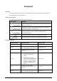
Foreword General This manual introduces the functions and operations of the network speed dome and PTZ camera (hereinafter referred to as "the Device"). Safety Instructions The following signal words might appear in the manual. Signal Words Meaning Indicates a high potential hazard which, if not avoided, will result in death or serious injury. Indicates a medium or low potential hazard which, if not avoided, could result in slight or moderate injury.
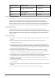
Revision Version Release Content Revision Time V2.0.0 Added some functions of the Baseline, and refine the whole manual. January 2020 V1.1.1 Updated some functions of the Security Baseline. September 2019 V1.0.0 First release. May 2018 Privacy Protection Notice As the device user or data controller, you might collect the personal data of others such as their face, fingerprints, and license plate number.
Important Safeguards and Warnings This section introduces content covering the proper handling of the Device, hazard prevention, and prevention of property damage. Read carefully before using the Device, comply with the guidelines when using it, and keep the manual safe for future reference. Operation Requirements ● Make sure that the power supply of the device works properly before use. ● Do not pull out the power cable of the device while it is powered on.
Table of Contents Foreword .............................................................................................................................................................I Important Safeguards and Warnings................................................................................................................ III 1 Network Configuration ................................................................................................................................... 1 1.
5 Setting ........................................................................................................................................................... 37 5.1 Camera .................................................................................................................................................. 37 5.1.1 Conditions Settings ...................................................................................................................... 37 5.1.1.1 Conditions ...............
5.2.6 UPnP ............................................................................................................................................. 78 5.2.7 Bonjour ......................................................................................................................................... 79 5.2.8 SNMP ............................................................................................................................................80 5.2.9 Multicast ...............................
5.4.2.12 Default .............................................................................................................................. 107 5.5 Event Management ............................................................................................................................. 108 5.5.1 Video Detection .......................................................................................................................... 108 5.5.1.1 Motion Detection .......................................
5.5.12.5 Battery Exception............................................................................................................. 150 5.6 Storage................................................................................................................................................ 151 5.6.1 Schedule ..................................................................................................................................... 151 5.6.1.1 Record ............................................
5.8.2.2 Remote Log ........................................................................................................................ 182 5.8.3 Online User ................................................................................................................................. 183 5.8.4 Life Statistics .............................................................................................................................. 183 5.8.5 Battery Status ..........................................
1 Network Configuration 1.1 Network Connection To view the web page on your PC, connect the Device to the PC first. There are mainly two connection modes between the Device and PC. The models presented in the figures are for reference only, and the actual product shall prevail. Figure 1-1 Direct connection by using a network cable Figure 1-2 Connection by using a switch or router All devices have the same IP address (192.168.1.108 by default) when they are delivered out of factory.
Step 2 Set the Country/Region, Language and Video Standard, and then click Save. Figure 1-3 Country/region setting Step 3 Configure time parameters, and then click Next. Figure 1-4 Time zone setting Step 4 Set the password for admin account, and then click Save.
Figure 1-5 Device initialization Table 1-1 Device initialization parameter description Parameter Description Username It is admin by default. Password The password should consist of 8 to 32 non-blank characters and contain at least two types of characters among upper case, lower case, number, and special characters (excluding ' " ; : &). Set a high security password according to the prompt of password strength. Make sure that the new password is the same as the confirming password.
Figure 1-7 P2P page Step 6 Scan the QR code on the page, download the app, and then finish configurations according to the instructions on your mobile device. After that, click Next. The Online Upgrade page is displayed. Figure 1-9 Online upgrade Step 7 Select Auto-check for updates checkbox. After the function is enabled, the Device will check for updates once a day automatically. There will be system notice if any update is available. Step 8 Click Next, and the login page is displayed.
Figure 1-10 Login page 1.2.2 First-time Login You need to download and install the plug-in for the first-time login. Step 1 Open the browser, enter the IP address of the Device in the address bar, and then press Enter. Step 2 Enter the username and password, and then click Login. ● If you enter the wrong password for 5 times, the account will be locked for 5 minutes. After the locked time, you can log in to the web page again. ● You can set the number of allowed password attempts and locked time in "5.
Figure 1-11 Install the plug-in Step 4 After the plug-in is installed, the web page will be refreshed automatically, and the video is displayed on the Live page. Figure 1-12 Live page The Live page shown in the manual is for reference only, and functions might be different depending on the model. 1.2.3 Device Login Step 1 Open the browser, enter the IP address of the Device in the address bar, and then press Enter.
Figure 1-13 Device login Step 2 Enter the username and password, and then click Login. The video is displayed on the Live page. ● If you enter the wrong password for 5 times, the account will be locked for 5 minutes. After the locked time, you can log in to the web page again. ● You can set the number of allowed password attempts and locked time. For details, see "5.5.12.3 Illegal Access". 1.2.
Figure 1-14 Login Step 2 Click Forgot password?, and the Prompt page is displayed. Figure 1-15 Prompt Step 3 Click OK to reset the password. The Reset the password (1/2) page is displayed. If you click OK, your email address, MAC address, device serial number, and other information might be collected.
Figure 1-16 Reset the password (1) Step 4 Scan the QR code on the actual page according to the instructions, and then enter the security code received in the mailbox. Reset the password with the security code you received within 24 hours, otherwise the code will be invalid. Step 5 Click Next. The Reset the password (2/2) page is displayed. Figure 1-17 Reset the password (2) Step 6 Set the password of the admin user again.
2 Live Click the Live tab, and the Live page is displayed. Figure 2-1 Live page Table 2-1 Function bars description No. Description 1 Encoding setting 2 Video window adjustment 3 System menu 4 Video window functions 5 PTZ configuration 6 PTZ status 2.1 Encoding Setting Click , and then select the stream as needed. Some devices do not support two sub streams.
Parameter Description Sub Stream 2 bandwidth. This option is normally used to replace main stream when bandwidth is not enough. Protocol Select a protocol for video monitoring. The supported protocols include TCP (Transmission Control Protocol), UDP (User Datagram Protocol), and Multicast. 2.2 Video Window Adjustment This section introduces the adjustment of video window. Figure 2-3 Video window adjustment Table 2-3 Description of Video window adjustment parameter No.
Image Adjustment This section introduces the adjustment of image. Figure 2-4 Image adjustment Table 2-4 Image adjustment parameter description Parameter Description Adjust the image brightness. Adjust the image contrast. Adjust the image hue. Adjust the image saturation. Restore brightness, contrast, saturation and hue to default values. Only brightness, contrast, hue, and saturation of live view image on the web interface can be adjusted with this function.
● You can adjust the size of the panoramic image by dragging the screen ratio bar ● You can click . to call a corresponding preset on the right side of the window. For how to set a preset, see "5.4.2.1 Preset". Figure 2-6 Preset ● You can click to call a corresponding tour on the right side of the window. For how to set a tour, see "5.4.2.2 Tour". Figure 2-7 Tour Face Face recognition result is displayed on the left side, and the captured face image and attributes are displayed on the right side.
Figure 2-9 Face recognition result display ● Face and attributes display area: Displays the captured small face pictures and information such as gender, age, and expression. After you click the picture, the details are displayed. Figure 2-10 Face and attributes display Video Metadata Motor vehicle information is displayed on the right side, and the information about human and nonmotor vehicles is at the bottom of the interface. For details, see "5.5.10 Video Metadata".
Figure 2-11 Video metadata 2.3 System Menu To access a certain page, click the corresponding tab on the system menu. Figure 2-12 System menu 2.4 Video Window Functions This section introduces the function of video window. Figure 2-13 Video window function buttons Table 2-5 Description of video window function button No. Parameter Description Click this button to select wiper operation. ● Start: Click this button, and the wiper starts and waves continuously.
No. Parameter Description Click this button, right-click on the Live interface, and the function menu is displayed. See Figure 2-14. You can add information on the Live interface, and also manage added comments. 2 Mark ● Add info: Select Add Info from the pop-up menu, and enter the comment. For the interface, see Figure 2-15. ● Manage comments: Select Info Management from the pop-up menu to display, hide, or delete added comments. For the interface, see Figure 2-16.
Figure 2-14 Mark—menu Figure 2-15 Mark—add comments Figure 2-16 Mark—manage comments 17
2.5 PTZ Configuration You can control PTZ by using the PTZ Control panel or joystick. You can also set preset, scanning, and other functions in the PTZ Function area. PTZ Control Before using the PTZ Control panel, you need to set the PTZ protocol by selecting Setting > PTZ > Protocol. Figure 2-17 PTZ control Table 2-6 Description of PTZ control parameter No. Parameter Description 1 Direction Buttons There are 8 directions: Up, down, left, right, upper left, upper right, lower left, and lower right.
Joystick You can drag the middle button to simulate joystick operations to control device rotation. Speed, zoom, focus, and iris configurations are the same as that of PTZ Control panel. Figure 2-18 Joystick PTZ Functions The PTZ supports multiple functions. Select a function, click using the function, and then click or to start to stop using the function.
Parameter Description Pattern Select Pattern from the list, enter a pattern number, and then click Start. The PTZ starts to pattern. Reserved for special requirements. Assistant If necessary, enable this function under the guidance of professionals. Pan Select Pan from the list, and then click Start. The PTZ starts to pan. ● Select Go to from the list, enter horizontal angle value, vertical angle value and zoom, and then click Go to. The Device will turn to the position you Go to want.
Figure 2-21 OSD menu You can finish the following settings through the menu. ● Camera settings: For details, see "5.1 Camera". ● PTZ settings: For details, see "5.4 PTZ Settings". ● System management: For details, see "5.7 System Management". 2.6 PTZ Status On the Live page, the PTZ status is displayed at the lower right corner. The function is available on select models. Figure 2-22 PTZ status When the PTZ lifespan is close to the threshold, a warning will be displayed on the Live page.
Figure 2-23 Warning (1) Figure 2-24 Warning (2) 22
3 AI Live You can check the information of the detected human faces, human bodies, motor vehicles, and nonmotor vehicles. This function is available on select models. 3.1 AI Live Page Log in and click the AI Live tab. Page might vary with different models. Figure 3-1 AI live page Table 3-1 Description of AI live page No. Function 1 Live view 2 Snapshot display area 3 Information display area of detected targets 4 Statistics area of the detected targets 3.1.
Figure 3-2 Information display of the detected targets 3.1.2 Snapshot Display Area This area displays the snapshots of the detected targets. Click any snapshot to view the information of the detected target in information display area. Figure 3-3 Snapshot display area 3.1.3 Statistics Area of the Detected Targets This area displays the number of the captured target in real time.
Figure 3-4 Statistics area of the detected targets Table 3-2 Statistics area description of the detected targets Icon Detected Target Description Face Available detection items: Gender, age, expression, glasses, mouth mask, and beard. Human Available detection items: Top, bottom, top color, bottom color, bag, hat, and umbrella. Non-motor vehicle Available detection items: Vehicle type, vehicle body color, top, top color, occupancy, and hat.
Figure 3-5 AI live page Step 2 Click to set the detection items of the targets. Figure 3-6 Detection items selection page Step 3 Click to complete the configuration.
4 Playback You can view the saved images and videos on the Playback page Before using the function, you need to set the period, storage method, and record control of recording and snapshot first. For details, see "5.6 Storage". Click the Playback tab, and the Playback page is displayed. Figure 4-1 Playback page 4.1 Video Playback Select dav from the File Type list, and the video playback interface is displayed. Figure 4-2 Video playback Table 4-1 Description of video playback parameter No.
No. Description 4 Auxiliary functions 5 Video playback file search and display area 6 Video clipping area 7 Progress bar time formats 4.1.1 Video Play Function Bar This section introduces the function of video play function bar. Figure 4-3 Video playing function bar Table 4-2 Description of video play function bar No. Parameter Description 1 Play Play the video. 2 Stop Stop playing the video. Play the next frame. 3 Next Frame You need to pause the playback before playing the next frame.
Figure 4-5 Auxiliary functions Table 4-3 Description of auxiliary functions parameter No. Parameter Description ● Click the button, and then select an area in the live view to zoom in; right-click on the image to restore to the original 1 Digital Zoom status. In zoomed-in status, drag the image to check other areas. ● Click the button, and then scroll the mouse wheel in the live view to zoom in or out.
Table 4-4 Description of playback file parameter (1) Parameter Description ● To play back a recording, select dav. File Type ● To play back an image, select jpg. Data Src The SD Card is used by default. Click this button, and recordings or images of a certain type on specific dates can be downloaded in batches. The function is available on select models. File list. Click this button, and the recording files on the selected day will be displayed in the list. 4.1.4.
Parameter Description Path Click Browse, and set the saving path for video files. The default path is C:\Users\admin\WebDownload\PlaybackRecord. Step 3 Click Search to search for the video files that meets the requirements. Step 4 Select the video, and then click Download. The video files are downloaded and saved in the saving path. You can select multiple files to download them. 4.1.4.
Figure 4-9 Playback file (2) Table 4-6 Description of playback file parameter (2) Parameter Description Search all the recorded files from the start time to the end time on the selected date. Download Format There are two options: dav and mp4. Click the download button, and the files will be saved to the storage path set in "5.1.2.5 Path". Downloading and playing video at the same time is not supported. Click the button to go back to the calendar interface. 4.1.
progress bar range. Step 2 Hover over , and then Select start time is displayed. Step 3 Click Step 4 Click the time axis to select the end time for video clipping. to set the start time for video clipping. The time must be within the progress bar range. Step 5 Hover over Step 6 Click Step 7 Click , and then Select end time is displayed. to set the end time for video clipping. , and the clipped video will be saved in the path set in "5.1.2.5 Path". 4.1.
Figure 4-12 Image playback Table 4-8 Description of image playback parameter No. Description 1 Image playing functions 2 Snapshot types 3 Image playback file search and display area 4.2.1 Image Playing Functions This section introduces the function of image playing. Figure 4-13 Image playing buttons The status button is displayed as by default, indicating the image play is paused or no image is being played.
Figure 4-14 Playback file (1) Table 4-9 Description of playback file parameter Parameter Description File Type Select jpg from the File Type list, and the image will be played in jpg.. Data Src The SD Card is selected by default. File list. Click this button, and the recording files on the selected day will be displayed in the list.
Figure 4-15 Playback file (2) Step 1 Click , and the snapshots on a selected day will be displayed in a list. Step 2 To play back a snapshot, double-click the corresponding file. Table 4-10 Description of playback file parameter Parameter Description Search all the snapshots from the start time to the end time on the selected date. Click the button to download the snapshot to local storage. Click the button to go back to the calendar page. 4.2.
5 Setting 5.1 Camera 5.1.1 Conditions Settings This section describes how to set camera attributes and manage profiles. 5.1.1.1 Conditions 5.1.1.1.1 Picture You can set camera attributes and picture parameters to achieve the best display effect. Step 1 Select Setting > Camera > Conditions > Conditions > Picture. Figure 5-1 Picture interface Step 2 Configure image setting parameter.
Parameter Description Brightness Set the overall image brightness. The larger the value is, the brighter the image will be. The value ranges from 0 to 100. Contrast Set the image contrast. The larger the value is, the greater the contrast will be. The value ranges from 0 to 100. Saturation Set the intensity of colors. The larger the value is, the brighter the colors will be. The value ranges from 0 to 100. The larger the value, the higher suppression on image colors. The value ranges from 0 to 100.
Figure 5-2 Exposure—auto mode Figure 5-3 Exposure—aperture priority mode 39
Figure 5-4 Exposure—shutter priority mode Figure 5-5 Exposure—gain priority mode 40
Figure 5-6 Exposure—manual mode Step 2 Configure exposure setting parameter. Table 5-2 Description of exposure setting parameter Parameter Description You can select 50Hz, 60Hz, or Outdoor from the list. ● 50Hz: When the alternating current is 50Hz, the exposure is automatically adjusted to make sure that there are no stripes on Anti-flicker images. ● 60Hz: When the alternating current is 60Hz, the exposure is automatically adjusted to make sure that there are no stripes on images.
Parameter Description Set the exposure modes. You can select Auto, Manual, Aperture Priority, Shutter Priority, or Gain Priority. The Auto mode is selected by default. ● Auto: Exposure is automatically adjusted according to scene brightness if the overall brightness of images is in the normal exposure range. ● Manual: You can adjust the Gain, Shutter, and Iris value manually. ● Aperture Priority: You can set the iris to a fixed value, and the Device Mode adjusts shutter value then.
5.1.1.1.3 Backlight The backlight function cannot be configured if defog function is enabled. There will be a prompt on the interface. You can use this function to adjust the backlight compensation mode of the monitoring screen. Step 1 Select Setting > Camera > Conditions > Conditions > Backlight. Figure 5-7 Backlight settings Step 2 Select a backlight mode from the list. There are 4 options: Off, BLC, HLC, and WDR. ● Off: Backlight is disabled.
Figure 5-8 WB settings Step 2 Select WB mode from the list. You can select from Auto, Indoor, Outdoor, ATW, Manual, Sodium Lamp, Natural, and Street Lamp. Auto is selected by default. Step 3 Click Save. 5.1.1.1.5 Day & Night This function allows you to switch between the color mode and the black & white mode, ensuring clear monitoring screen in a dim environment. Defog function cannot be configured if Day & Night function is enabled. There will be a prompt on the interface.
Figure 5-9 Day & night settings Step 2 Configure day & night parameter. Table 5-3 Description of day & night parameter Parameter Description There are two options: Electrical and ICR. ICR is selected by default. ● Electrical Image processing method is used for day & night switch. Type ● ICR: IR filter is used for day & night switch. Select a mode from the list (Your selection is independent from the profile). Auto is selected by default. ● Color: The Device only outputs color images.
blurrier the images will become. Step 1 Select Setting > Camera > Conditions > Conditions > Focus & Zoom. Figure 5-10 Focus & zoom settings Step 2 Configure focus & zoom parameter. Table 5-4 Description of focus & zoom parameter Parameter Description Digital Zoom Select On or Off to enable or disable digital zoom. Off is selected by default. Zoom Speed The larger the value is, the faster the Device zooms. Select the focus triggering mode. There are three options: Semi Auto, Auto, and Manual.
Parameter Description Lens Initialization Click this button, and the lens will be initialized automatically. The lens will be extended to calibrate the zoom and focus. Step 3 Click Save. 5.1.1.1.7 Illuminator This configuration is available only when the device is equipped with illuminators. Common illuminators are classified into IR lights, white lights, laser lights, and full-spectrum lights. Different device models support different types of illuminators.
Step 2 Configure illuminator parameters. Table 5-5 Description of illuminator parameters Parameter Description IR Mode White Mode When the device is equipped with illuminators, you can configure the fill light mode, including IR mode, white light and smart illumination. ● IR Mode: Enable the IR light, and then the white light is disabled. You can only capture black and white images after enabling this function. The IR light is turned off for cameras with low power consumption by default.
Parameter Description The system adjusts the illuminator intensity according to the ambient lighting condition. Some devices support setting the brightness upper limit and sensitivity of the illuminator. ● Sensitivity: The higher the sensitivity setting, the higher the brightness can turn on the illuminator when the actual scene darkens. When the actual scene becomes bright, a higher brightness is required Auto to turn off the illuminator.
Laser Light Laser light makes compensation for the ambient environment when it is used for long-distance monitoring. Step 1 Select Setting > Camera > Conditions > Conditions > IR Light. Figure 5-12 Laser light settings Step 2 Configure laser light setting parameter. Table 5-6 Description of laser light setting parameter Parameter Description Mode Select the laser light mode from ZoomPrio and Manual. It is ZoomPrio by default.
Figure 5-13 Defog settings—manual Figure 5-14 Defog settings—auto Step 2 Configure defog parameter.
Table 5-7 Description of defog parameter Parameter Description Select the defog mode of the Device. You can select Auto, Manual, or Off. It is Off by default. Mode For the Device that supports optical defog, in Auto mode, optical defog and electronic defog switch automatically according to the algorithm. And in Off mode, electronic defog is enabled by default. Set the defog intensity of the Device. You can select from Low, Medium, or High.
6:00 to 18:00, and set the night-time configuration from 18:00 to 6:00 on the next day. Figure 5-17 Profile management—schedule Step 3 Click Save. 5.1.2 Video You can set the video stream, snapshot stream, video overlay, ROI, and storage path of the Device. 5.1.2.1 Video Stream This section describes how to set the video stream for the monitoring screen. Step 1 Select Setting > Camera > Video > Video.
Parameter Description Enable Smart Codec to improve video compressibility and save storage space. Smart Codec After Smart Codec is enabled, the Device does not support the third stream, ROI, smart event, and other functions. Resolution Multiple resolution types are available for you to choose, and each type corresponds to a unique recommended stream value. Frame Rate (FPS) PAL: 1–25 frames/s or 1–50 frames/s. The frame rate changes with the resolution.
Figure 5-19 Snapshot stream settings Step 2 Configure snapshot stream parameter. Table 5-9 Description of snapshot stream parameters Parameter Description You can select General or Event. ● General refers to capturing images within the time range set in the schedule. For details, see "5.6.1 Schedule". Snapshot Type ● Event means capturing images when motion detection, video tampering, or local alarms are triggered.
Figure 5-20 Privacy masking Step 2 Select Enable. Step 3 Click Add, select the masking type and color, set the shielding ratio, and then draw blocks on the image. You can select the masking type from Color Lump and Mosaic. ● When selecting Color Lump only, you can draw triangles and convex quadrilaterals as blocks. You can drag 8 blocks at most. ● When selecting Mosaic, you can draw rectangles as blocks with mosaic. You can draw 4 blocks at most.
Figure 5-21 Channel title Step 2 Select the Enable checkbox, enter the channel title, and then select the text alignment. Click to expand the channel title, and you can expand 1 line at most. Step 3 Move the title box to the position that you want in the image. Step 4 Click Save. 5.1.2.3.3 Time Title You can enable this function when you need to display time in the video image. Step 1 Select Setting > Camera > Video > Overlay > Time Title.
5.1.2.3.4 OSD Info You can enable this function if you want to display preset title, temperature, PTZ life warning, coordinates, zoom, north direction, pattern, RS-485, battery information, and other information on the video image. Step 1 Select Setting > Camera > Video > Overlay > OSD Info. Figure 5-23 OSD info Step 2 Configure OSD information.
Parameter Description RS485 Select Enable, and the RS-485 communication information is displayed on the image. Battery Info Select Enable, and the battery level is displayed on the image. Text Overlay Input Text Text Align Select Enable and enter text, and the text is displayed on the image. Set the alignment mode of the displayed information on the image. Step 3 Move the OSD box to the position that you want on the image. Step 4 Click Save. 5.1.2.3.
Figure 5-25 Picture overlay Step 2 Select the Enable checkbox, click Upload Picture, and then select the image to be overlaid. The image is displayed on the video image. Step 3 Move the overlaid image to the position that you want on the image. Step 4 Click Save. 5.1.2.3.7 Mobile State You can enable this function if you want to display mobile state on the image. Step 1 Select Setting > Camera > Video > Overlay > Mobile State. Figure 5-26 Mobile state Step 2 Select the Enable checkbox.
5.1.2.3.8 Custom Overlay You can enable this function if you need to display custom information on the video image. Step 1 Select Setting > Camera > Video > Overlay > Custom Overlay. Figure 5-27 Custom overlay Step 2 Select the Enable checkbox, and then select the text alignment. Click to expand the custom overlay, and you can expand 1 line at most. Step 3 Drag the custom overlay box to the position that you want on the image. Step 4 Click Save. 5.1.2.3.
Step 4 Click Save. The exception information is displayed on the image. 5.1.2.3.10 Latitude and Longitude You can enable this function if you need to display latitude and longitude on the video image. Step 1 Select Setting > Camera > Video > Overlay > Latitude and Longitude. Figure 5-29 Latitude and longitude Step 2 Select the Enable checkbox. Step 3 Drag the box to the position that you want on the image. Step 4 Click Save. 5.1.2.
Figure 5-30 ROI settings Step 2 Select Enable to enable this function. Step 3 Press and hold the left mouse button to draw boxes on the monitoring screen. You can draw up to 4 boxes. ● Click Delete or right click to delete the drawn boxes. ● Click Remove All to clear all boxes. Step 4 Set the image quality of the ROI. Step 5 Click Save. 5.1.2.5 Path The storage path is associated with the snapshot and recording on the Live page. You can set the path of Live Snapshot and Live Record respectively.
Figure 5-31 Path settings Step 2 Set each storage path. ● Default storage path for snapshots: C:\Users\admin\WebDownload\LiveSnapshot. ● Default storage path for recording: C:\Users\admin\WebDownload\LiveRecord. ● Default storage path for playback snapshot: C:\Users\admin\WebDownload\PlaybackSnapshot. ● Default storage path for playback download: C:\Users\admin\WebDownload\PlaybackRecord. ● Default storage path for video clips: C:\Users\admin\WebDownload\VideoClips. Step 3 Click Save. 5.1.
Figure 5-32 Audio Step 2 Enable audio in main stream or sub stream. Step 3 Configure audio parameters. Table 5-11 Description of audio parameter Parameter Description Enable audio in main stream or sub stream. Enable Audio can be enabled only when video has been enabled. Encode Mode The audio encoding mode selected here applies to both audio streams and voice talks. We recommend you to keep the default value. Sampling Frequency The number of audio signals sampled per second.
Parameter Description Set the audio output type. ● LineOut: The Camera outputs audio signals through an external audio device. ● Speaker: The Camera outputs audio signals through the built-in Audio Output Type speaker. ● Bluetooth: The Camera outputs audio signals through a Bluetooth device. Bluetooth is available on select models. Noise Filter After the function is enabled, noise in the environment will be filtered. Adjust the noise reduction level.
Click Stop to complete recording. ● Select Upload, click , select the audio file to be uploaded, and then click Upload. ● The format of recorded audio is .pcm. Audio recording is only supported by some devices. ● Audio file in the format of .wav can be uploaded. ● You can edit and delete recorded or uploaded audio. Step 4 ◇ Click to ◇ Click edit audio file. to delete audio file. Select the audio file that you need. Related Operations ● Play audio: Click to play the alarm audio.
Figure 5-35 TCP/IP settings Step 2 Set TCP/IP parameters. Table 5-12 Description of TCP/IP parameter Parameter Description Host Name Set the name of the current device. The host name can be English or Chinese within 63 bytes. Select the Ethernet card to be configured. Wire is selected by default. Ethernet Card If the Device is configured with multiple Ethernet cards, the default Ethernet card can be changed. If you reset the default Ethernet card, restart the Device.
Parameter Description IP Version You can select IPv4 or IPv6. Both versions are supported and can be accessed. IP Address Enter correct digits to change the IP address. Set the subnet mask according to actual conditions. The subnet prefix is a number in the range of 1 to 255. The subnet prefix identifies a specific network link, and usually contains a hierarchical structure. Subnet Mask The Device checks the validity of all IPv6 addresses.
1. To obtain a usable IP address, make sure that the Device and your PC are in the same LAN. 2. Get the MAC address from the Device label. 3. Open command editor on the PC and enter the following command. Table 5-13 Command list System Command arp -s Windows syntax ping -l 480 -t < IP Address > Example: arp -s 192.168.1.125 11-40-8c-18-10-11 ping -l 480 -t 192.168.0.125 arp -s ping -s 480 < IP Address > UNIX/Linux/Mac syntax Example: arp -s 192.168.1.
System Command arp -s UNIX/Linux/Mac syntax ping -s 480 < IP Address > Example: arp -s 192.168.1.125 11-40-8c-18-10-11 ping -s 480 192.168.0.125 netsh i i show in netsh -c“i i” add neighbors ldx Win7 syntax ping -l 480 -t < IP Address > Example: netsh i i show in netsh -c“i i” add neighbors 12 192.168.1.125 11-40-8c-18-10-11 ping -l 480 -t 192.168.1.125 Step 4 Power off the Device and then restart it, or restart the Device over the network.
● Except Max Connection, modifications of other parameters will take effect after restart. ● 0–1024, 1900, 3800, 5000, 5050, 9999, 37776, 37780–37880, 39999, and 42323 are occupied for specific uses. ● It is not recommended to use the default values of other ports during port configuration. Table 5-15 Description of port parameter Parameter Description Max Connection The maximum number of users that can log in to the web page of the Device simultaneously.
Parameter Description A network protocol for real-time data communication. The value is 1935 by default. You can enter the value as needed. RTMP Enable RTMP to push audio and video data to the third-party server. Make sure that the address is trusted; otherwise it might cause data leakage. HTTPS Port HTTPS communication port. The value is 443 by default. You can set this parameter as needed. The port is disabled by default.
Figure 5-38 PPPoE page (2) 5.2.4 DDNS Properly configure DDNS, and then the domain name on the DNS server matches your IP address and refresh the matching relation in real time. You can always access your device with the same domain name no matter how much your device IP address changes. Before making any changes, check whether your device supports the DNS server. ● The third party servers might collect your device information if DDNS is enabled.
Parameter Description relationship. ● CN99 DDNS Server address: www.3322.org Server Address ● NO-IP DDNS Server address: dynupdate.no-ip.com ● Dyndns DDNS Server address: members.dyndns.org Domain Name The domain name you registered on the DDNS website. Username Enter the username and password obtained from DDNS service provider. You need to register an account (including username and password) on the website of DDNS service provider.
Figure 5-40 SMTP (Email) Step 2 Configure SMTP (Email) parameter. Table 5-17 Description of SMTP (Email) parameter Parameter Description SMTP Server IP address of the outgoing mail server complying with SMTP protocol. Port Port number of the outgoing mail server complying with SMTP protocol. It is 25 by default. Username Username of sender mailbox. Password Password of sender mailbox.
Parameter Description Select authentication type from None, SSL and TLS. TLS is selected by default. Authenticati on ● For the detailed configuration, see Table 5-18. ● There might be risks if you select the authentication type other than TLS. TLS is recommended. Title You can enter no more than 63 characters in Chinese, English, and Arabic numerals. Mail Receiver Email address of the receiver. Support 3 addresses at most. Attachment Select the checkbox to support attachment in the email.
Type SMTP Server Authentication Port Description mailbox. ● The authentication code is required; the email password is not applicable. — Authentication code is the code you receive when enabling SMTP service. Sina smtp.sina.com 126 smtp.126.com Step 3 SSL 465 — 25 — 25 You need to enable SMTP service in your mailbox. You need to enable SMTP service in your mailbox. Click Save. 5.2.6 UPnP After UPnP is enabled, Intranet service and port of the Device will be mapped to Extranet.
Configuring UPnP 1. Select Setting > Network > UPnP. Figure 5-41 UPnP 2. Select Enable. 3. Select a mode from the drop-down list. There are 2 mapping modes: Custom and Default. ● In Custom mode, users can modify the external port. ● Select Default, and then the system finishes mapping with unoccupied port automatically. In this case, you do not need to modify mapping relation. 4. Select Start Device Discover. 5. Click Save. 5.2.
Configuring Bonjour 1. Select Setting > Network > Bonjour. Figure 5-42 Bonjour page 2. Select Enable, and then set Server Name. 3. Click Save. Visiting Web Page with Safari Browser In the OS and clients that support Bonjour, perform the following steps to visit the web page of the Device with Safari browser. 1. Click Show all bookmarks in Safari. 2. The OS or client automatically detects the network cameras with Bonjour enabled in the LAN. 3. Click to visit the corresponding web page. 5.2.
Figure 5-43 SNMP (1) Figure 5-44 SNMP (2) Step 2 Select SNMP version to enable SNMP. ● Select V1, and the system can only process information of V1 version. ● Select V2, and the system can only process information of V2 version. ● Select V3, and then V1 and V2 become unavailable. You can configure username, password and authentication type. It requires corresponding username, password and authentication type to access your device from the server.
Using V1 and V2 might cause data leakage, and V3 is recommended. In Trap Address, enter the IP address of the PC that has MIB Builder and MG-SOFT MIB Browser installed, and leave other parameters to the default. Table 5-19 Description of SNMP parameters Parameter Description SNMP Port The listening port of the software agent on the Device. The read and write community string that the software agent supports.
Use PC with Windows OS and disable SNMP Trap service. The MG-SOFT MIB Browser will display prompt when an alarm is triggered. 5.2.9 Multicast You can access the Device by network to see live view. If the access times exceed its upper limit, preview might fail. You can set multicast IP to access by multicast protocol to solve the problem. The Device supports two multicast protocols: RTP and TS. RTP is enabled by default when main stream and sub stream are used. TS is disabled by default. 5.2.9.
5.2.10 Auto Register After you enable this function, when the Device is connected to Internet, it will report the current location to the specified server which acts as the transit to make it easier for the client software to access the Device. Step 1 Select Setting > Network > Auto Register. Figure 5-47 Auto register Step 2 Select the Enable checkbox to enable Auto Register. Step 3 Enter IP Address, Port and Sub-Device ID.
Figure 5-48 Wi-Fi settings (1) Step 2 Click Search SSID, and Wi-Fi hotspots in the environment of current network camera are displayed. Figure 5-49 Wi-Fi settings (2) Step 3 To manually add Wi-Fi, click Add SSID. Figure 5-50 Add Wi-Fi Step 4 Enter a network name in the dialog box. It is recommended to set a secure encryption method for the Device to connect routers. Step 5 Double-click one hotspot to display the Signal Quality and the Authentication Manner.
5.2.11.2 WPS Settings Figure 5-51 WPS settings PIN and SSID can be obtained from the router. Enter PIN and SSID, and then click Refresh to display operating status in real time. 5.2.11.3 AP Settings You can use the Camera as wireless AP (Access Point), and other devices such as mobile phones can connect to the Camera by searching for the network name. You can then log in to the Camera through the browser on your device. At most 5 accounts can log in to the Camera at the same time.
Parameter Description Host IP Displays the IP address of AP. Step 3 Click Save. Result 1. Open your device such as mobile phone, search for the network name of the AP in the wireless signal list, and then connect to the network. After it is successfully connected, the IP address and MAC address of the device is displayed on the AP interface. 2.
5.2.13 QoS QoS (Quality of Service) is a network security mechanism, and is also a technology to solve network delay, congestion, and other problems. For network business, QoS includes transmission bandwidth, time delay in transmission, and packet loss of data. In network, QoS can be improved by ensuring transmission bandwidth, and reducing time delay in transmission, packet loss rate, and delay jitter. For DSCP (Differentiated Services Code Point), there are 64 priority degrees (0–63) of data packets.
● The function is available on devices with 4G/5G module. This section uses 4G as an example. ● Dual 4G is supported by select models, but only one 4G network adapter can be enabled simultaneously. 5.2.14.1 Dialing Setting Log in to web page, select Setting > Network > 4G > Dialing Setting. Figure 5-55 Dialing setting page Some devices only support certain mobile carriers, and only the supported carriers are displayed in Network Support. Step 1 Select the Enable checkbox.
● If the current time is in the period you set, 4G network connection will be enabled. The IP address of the SIM card will be displayed in IP Address. And you can access the device through 4G after finishing the rest steps. ● If the current time is not in the period you set, 4G network connection will not be enabled. Only the corresponding Wireless Signal is displayed on the page. And you cannot access the device through 4G.
Make sure that you add international calling codes before the phone number to avoid unnecessary charges caused by phone calls or messages to other countries or regions. Figure 5-57 Mobile setting page ● Message Send: When alarms are triggered, the phone number added will receive message. ● Message Activation: You can enable 4G through message outside the period you set to use 4G. You need to send "ON" or "OFF" to phone number of the SIM card in the Device.
Figure 5-58 Message link Step 5 Click Save on the page of the corresponding event. You will receive message if the alarm is triggered. 5.2.15 Access Platform 5.2.15.1 P2P P2P is a private network traversal technology which enables users to manage devices easily without requiring DDNS, port mapping or transit server. Scan the QR code with your smart phone, and then you can add and manage more devices on your mobile client. Step 1 Select Setting > Network > Access Platform > P2P.
Figure 5-59 P2P page ● P2P is enabled by default. You can manage the devices remotely. ● When P2P is enabled and the device is connected to network, the status is displayed as Online. We might collect the information including IP address, MAC address, device name, and serial number. The information collected is for remote access only. If you do not agree with this, you can clear the Enable checkbox. Step 2 Log in to mobile phone client, and then tap Device Management.
5.2.15.3 RTMP You can connect the third party platforms (such as YouTube) to play live video through RTMP protocol. ● Only admin user can configure RTMP. ● RTMP only supports H.264, H.264B and H.264H video formats, and Advanced Audio Coding (AAC) audio format. Step 1 Select Setting > Network > Access Platform > RTMP. Figure 5-61 RTMP page Step 2 Select the Enable checkbox to enable RTMP. When enabling RTMP, make sure that the address can be trusted. Step 3 Set RTMP parameters.
5.3 Bluetooth Settings You can connect the Camera to Bluetooth devices such as Bluetooth headset for voice broadcast of alarms and voice intercom with the platform. The function is available on select models. Procedure Step 1 Select Setting > Connection Settings > Bluetooth. Step 2 Select Enable. The searched Bluetooth devices are displayed in the Bluetooth List. Click Refresh at the lower-right corner of the list to search for Bluetooth devices again.
Figure 5-64 Set audio Related Operations ● Click Refresh at the lower-right corner of the list to get information of paired Bluetooth devices again. ● Click Pair Again to quickly connect to Bluetooth devices paired before. ● Click Delete to delete the Bluetooth device. 5.4 PTZ Settings 5.4.1 Protocol Network PTZ setting and analog PTZ setting are available on select models. 5.4.1.1 Network PTZ Settings Step 1 Select Setting > PTZ > Protocol > Network PTZ.
Figure 5-65 Network PTZ setting Step 2 Select a protocol. You can select DH-SD1, DH-SD3, PELCOD, or PELCOP. DH-SD1 is selected by default. DH-SD1 protocol supports up to 80 presets, and DH-SD3 protocol supports up to 300 presets. Step 3 Click Save. 5.4.1.2 Analog PTZ Settings Step 1 Select Setting > PTZ > Protocol > Analog PTZ. Figure 5-66 Analog PTZ setting Step 2 Configure analog PTZ parameter. Table 5-25 Description of analog PTZ parameter Parameter Description Enter the address of the Device.
5.4.2 Function 5.4.2.1 Preset Select Setting > PTZ > Function > Preset. The Preset page is displayed. If you click Remove All, all presets and special presets will be cleared. Figure 5-67 Preset 5.4.2.1.1 Preset Settings Preset means a certain position to which the Device rotates. Users can adjust the PTZ and camera to the location quickly through calling presets.
Step 3 Click to save the preset. Step 4 Perform operations on presets. ● Double-click the preset title to edit the title displayed on the monitoring screen. ● Click to delete the preset. 5.4.2.1.2 Special Preset Settings Special presets serve as the shortcut for some special functions switch or calling, and they no longer represent the location of the PTZ camera. Step 1 Click to add a special preset. The added special preset will be displayed in the list.
You need to set several presets in advance. Step 1 Select Setting > PTZ > Function > Tour. Figure 5-70 Tour settings Step 2 Select the Tour Mode from Original Path and Shortest Path. Original Path is selected by default. ● Original Path: Tour in the order of adding presets. ● Shortest Path: Starting from the preset with largest horizontal zoom value and vertical zoom value, pass all presets in the tour to ensure the shortest path.
limits. Step 1 Select Setting > PTZ > Function > Scan. Figure 5-71 Scan settings Step 2 Select the Scan No.. Step 3 Drag the slider to adjust the scan speed. Step 4 Click Setup to adjust the Device to an ideal position. Step 5 Click Set Left Limit and Set Right Limit to set the left and right boundaries of the Device. Step 6 Click Start, and then the Device starts scanning. Step 7 Click Stop, and then the scanning stops. 5.4.2.
Figure 5-72 Pattern settings Step 2 Select the Pattern No.. Step 3 Click Setup and Start Rec, and then operate the PTZ. Step 4 Click Stop Rec to stop recording. Step 5 Click Start, and then the Device starts patterning. Step 6 Click Stop, and then the patterning stops. 5.4.2.5 Pan Pan refers to the continuous 360° rotation of the Device at a certain speed. Step 1 Select Setting > PTZ > Function > Pan.
Step 2 Drag the slider to set the Pan Speed. Step 3 Click Start, and the Device starts to rotate horizontally at this speed. 5.4.2.6 PTZ Speed You can adjust the manual control speed of the PTZ by setting PTZ speed. This speed does not apply to tour, pattern, or auto tracking. Step 1 Select Setting > PTZ > Function > PTZ Speed. Figure 5-74 PTZ speed settings Step 2 Select Low, Middle or High. 5.4.2.
Figure 5-75 Idle motion settings Step 2 Select the Enable checkbox to enable the idle motion. Step 3 Select idle motion from Preset, Tour, Scan and Pattern. Step 4 Select the action number of the selected motion. Step 5 Set Idle Time for the selected motion. Step 6 Click Save. 5.4.2.8 PowerUp PowerUp means the automatic operation of the Device after it is powered on. Set Preset, Tour, Scan or Pattern in advance. Step 1 Select Setting > PTZ > Function > PowerUp.
Figure 5-76 PowerUp settings Step 2 Select the Enable checkbox to enable power up motion. Step 3 Select power up motion from Preset, Tour, Scan, Pattern or Auto. Select Auto and the last motion before you shut down the Device last time will be performed. Step 4 Select the action number of the selected motion. Step 5 Click Save. 5.4.2.9 PTZ Limit After you set the PTZ limit, the Device can only move in the defined area. Step 1 Select Setting > PTZ > Function > PTZ Limit.
Step 2 Adjust the PTZ direction, and then click Setting to set the Up Line. Step 3 Adjust the PTZ direction, and then click Setting to set the Down Line. Step 4 Click Live to preview the already-set up line and down line. Step 5 Select the Enable checkbox to enable the PTZ limit function. 5.4.2.10 Time Task After you set time task, the Device performs the selected motions during the defined period. Set Preset, Tour, Scan or Pattern in advance. Step 1 Select Setting > PTZ > Function > Time Task.
Figure 5-79 PTZ restart Step 2 Click PTZ Restart. The PTZ is restarted. 5.4.2.12 Default With the function, you can restore the PTZ to factory defaults. This function will restore the Device to defaults. Think twice before performing the operation. Step 1 Select Setting > PTZ > Function > Default.
Figure 5-80 Default setting Step 2 Click Default. The PTZ will be restored to factory defaults. 5.5 Event Management 5.5.1 Video Detection Video detection includes three event types: Motion Detection, Video Tamper and Scene Changing. 5.5.1.1 Motion Detection When the moving object appears and moves fast enough to reach the preset sensitivity value, alarms will be triggered. Step 1 Select Setting > Event > Video Detection > Motion Detection.
Figure 5-81 Motion detection settings Step 2 Select the Enable checkbox, and then configure motion detection parameters. ● Set arming and disarming period. 1. Click Setting, and then set the arming period on the page.
Figure 5-82 Arming period settings 2. Set the alarm period to enable alarm events in the period you set. ◇ There are 6 time periods for each day. Select the check box for the time period to enable it. ◇ Select the day of week (Sunday is selected by default; If All is selected, the setting is applied to the whole week. You can also select the check box next to the day to set it separately). 3. After completing the settings, click Save. You will return to the Motion Detection page. ● Set the area.
Figure 5-83 Area setting Table 5-26 Description of area setting parameter Parameter Description Name The default names are Region1, Region2, Region3 and Region4, and the names can be customized. Sensitivity Sensitivity to brightness change. The higher the sensitivity is, the easier the motion detection event will occur. You can set different sensitivities for each region, with values ranging from 0 to 100, and 30 to 70 is recommended. Threshold Detect the relation between the object and the region.
Parameter Description Record After you enable the function, when an alarm is triggered, the system will start recording automatically. Before using the function, you need to set the recording period of the alarm in Storage > Schedule, and select Auto for Record Mode on the Record Control page. Record Delay When the alarm is over, the alarm recording will continue for an extended period of time. The time unit is second, and the value range is 10–300.
For parameters configuration, see "5.5.1.1 Motion Detection". Step 3 Click Save. 5.5.1.3 Scene Changing Alarms will be triggered if there is scene changing. Step 1 Select Setting > Event > Video Detection > Scene Changing. Figure 5-85 Scene changing settings Step 2 Select the Enable checkbox, and then configure scene changing parameters. For parameters configuration, see "5.5.1.1 Motion Detection". Step 3 Click Save. 5.5.
● The function depends on the result of motion detection, and all other parameters (except sensitivity) of motion detection function are used, including arming period, area settings, and linkage configurations. If no motion detection is triggered, smart motion detection will not be triggered. ● If motion detection is not enabled, when smart motion detection is enabled, motion detection will also be enabled.
Figure 5-87 Audio detection settings Step 2 Configure audio detection parameter. Table 5-28 Description of audio detection parameter Parameter Description Input Abnormal Select Input Abnormal, and then an alarm is triggered when there is abnormal audio input. Intensity Change Select Intensity Change, and then an alarm is triggered when the change in sound intensity exceeds the defined threshold. Sensitivity The value ranges from 1 to 100.
For other parameters, see "5.5.1.1 Motion Detection". Step 3 Click Save. 5.5.4 Smart Plan Smart plans include IVS, face recognition, heat map, people counting, video metadata, construction monitoring and so on. Only after smart plans have been enabled, can the corresponding smart function come into effect. Before configuring the smart plan, you need to set presets in advance. For setting methods, see "5.4.2.1 Preset". Step 1 Select Setting > Event > Smart Plan.
Figure 5-89 Smart plan (2) Step 5 Click Save. 5.5.5 IVS Basic Requirements for the Scene ● The target size shall not exceed 10% of the image. ● The pixel of the target shall be no less than 10×10; the pixel of abandoned object shall be no less than 15×15 (CIF image); the width and height of the target shall be no more than 1/3 of the image. It is recommended that the height of the target is 10% of the image. ● The brightness difference between the target and the background is no less than 10 gray values.
Rule Config 1. Select Setting > Event > IVS > Rule Config. Figure 5-90 Add smart rules 2. Select the presets to be configured with smart rules. 3. Click to add smart rules. Double-click rule type to modify the type of rules. 4. Click Save. 5.5.5.1 Tripwire Alarms are triggered when the target crosses the warning line in the defined direction.
Figure 5-91 Tripwire rule settings Step 2 Click Draw Rule, and you can draw rules on the monitoring screen. Click Clear to the right of Draw Rule to clear all drawn rules. Table 5-29 Description of rule drawing parameter Parameter Description Max Size Set the size range of detection targets to be filtered, and select the maximum or minimum size. ● Max Size: Set the maximum size of targets to be filtered. When the Min Size Pixel Counter target is larger than this size, the system will ignore it.
Step 3 Configure tripwire parameter. Table 5-30 Description of tripwire parameter Parameter Description Set the alarming period to enable alarm events in the defined period. 1. Click Setting, and then the Period interface is displayed. 2. Enter the time value or press and hold the left mouse button, and drag directly on the setting interface. There are six periods for each day. Period Select the checkbox next to the period for it to take effect. 3.
reserved at the periphery of the area line. Applicable scenes: Scenes with sparse targets and no occlusion between targets, such as perimeter protection of unattended areas. Step 1 Select Intrusion from the Rule Type list. Figure 5-92 Intrusion settings Step 2 Click Draw Rule, and you can draw rules on the monitoring screen. For parameter description, see Table 5-29. Click Clear to the right of Draw Rule to clear all drawn rules. Step 3 Configure intrusion parameter.
Pedestrians or vehicles that stay for too long would be regarded as abandoned objects. To filter out such alarms, you can use Target filter. In addition, the duration can be properly extended to avoid false alarm due to a short stay of people. Applicable scenes: Scenes with sparse targets, no obvious and frequent light changes. For scenes with intensive targets or too many obstacles, missed alarms would increase; for scenes in which too many people stay, false alarms would increase.
5.5.5.4 Missing Object An alarm will be triggered when the selected target in the scene is taken away for the time longer than the set duration. The system analyzes static areas from the foreground, and determines whether it is missing object or abandoned object from the similarity of its foreground and background. When the time exceeds the set period, an alarm is triggered. Applicable scenes: Scenes with sparse targets, no obvious and frequent light changes.
For other parameters, see "5.5.5.1 Tripwire". Step 4 Click Save. 5.5.6 Construction Monitoring The Device can be used for construction monitoring which include helmet detection, workwear detection, lone working detection and absence detection. Prerequisites Select Setting > Event > Smart Plan to enable Construction Monitoring. Procedure Step 1 Select Setting > Event > Construction Monitoring. Step 2 Select Global or a preset from the Preset list.
Figure 5-96 Plan by preset Step 3 Click at the upper-right corner of the Area Config section. Double click the rule name to modify it. Step 4 Click to draw rule box on the video image, and then right-click to complete drawing. ● After drawing is complete, drag the corners of the drawn area to adjust the detection area. ● If you select preset plan, 8 detection areas can be drawn at most. Step 5 Select the checkbox before the event type to enable the corresponding detection rule.
Figure 5-97 Helmet detection Figure 5-98 Workwear detection 126
Figure 5-99 Lone working detection Figure 5-100 Absence detection Table 5-35 Parameter description Parameter Description Allowed Color When configuring helmet detection, you can set allowed colors. When the helmet detected is not in the selected colors, alarms will be triggered. Duration When events not following the rule are detected and the duration exceeds the defined value, alarms will be triggered.
Parameter Description Repeat Alarm Time After an alarm is triggered, when the event lasts for the time reaching repeated alarm time, an alarm will be triggered again. Record After you enable the function, when an alarm is triggered, the system will start recording automatically. Before using the function, you need to set the recording period of the alarm in Storage > Schedule, and select Auto for Record Mode on the Record Control interface.
● Select Setting > Event > Smart Plan to enable face recognition. ● This function is available on select models. 5.5.7.1 Face Detection When human face is detected in the monitoring screen, an alarm is triggered and the linked action is performed. Step 1 Select Setting > Event > Face Recognition > Face Detection. Figure 5-101 Face detection page Step 2 Select Enable to enable the face detection function. Step 3 Configure face detection parameters.
Parameter Description Send Email Select Send Email, and when alarms are triggered, the system sends email to the specified mailbox. For the email settings, see "5.2.5 SMTP (Email)". Select Snapshot, and the system takes snapshot when alarms are triggered. Snapshot ● Enable the motion detection snapshot first. For details, see "5.6.1.1 Record". ● For searching and setting snapshot storage path, see "5.1.2.5 Path". Snap Face Image Set the snapshot scope, including Face and One-inch photo.
Figure 5-104 Add face database completed Step 5 Configure face database configuration parameters. Table 5-37 Description of face database config parameter Parameter Description Deploy Select Deploy and the face database takes effect. Similarity Threshold The comparison is successful only when the similarity between the detected face and the face feature in face database reaches the set similarity threshold. After this, the comparison result is displayed on the Live page.
Figure 5-106 Registration interface Step 4 Click Upload Picture, and then import the face pictures to be uploaded. You can manually select a face area. After uploading the picture, select a face area and click OK. If there are multiple faces in an image, select the target face and click OK to save the face image.
Figure 5-107 Addition completed Step 5 Fill in face image information. Step 6 Click Add to task list. Step 7 Click . Figure 5-108 Task list addition completed Click Remove All to remove all the tasks. Batch Registration You can import multiple face images in batches. Use this method when registering a large number of face images. Before importing images in batches, name the face images in the format of "Name#SGender#BDate of Birth#NRegion#TCredentials Type#MID No.
Name is required and the rest are optional. Table 5-38 Naming rules for batch import Naming Rules Description Name Enter the corresponding name. Gender Enter a number. 1: Male; 2: Female. Date of Birth Enter numbers in the format of yyyy-mm-dd. For example, 2017-11-23. Region Enter the region name. Credentials Type Enter a number. 1: ID card; 2: passport. ID No. Enter ID No. Step 1 Select Setting > Event > Face Recognition > Face Database Config.
Figure 5-110 Batch registration Step 5 Click Browse. Figure 5-111 Registering Step 6 After the registration is completed, click Next to view the registration result. 5.5.7.2.3 Managing Face Images You can add face images to face database; manage and maintain face images to ensure correct information. Modifying Face Information On the Face Database Config page, move the mouse pointer to the face image or person information line, and then click or .
Figure 5-112 Registration page Deleting Face Images Enter face database, and then delete the created face image. ● Single deletion: Move the mouse pointer to the face image or people information line, and then click or to delete the face image. ● Batch deletion: Move the mouse pointer to the face image or people information line, and then click at the upper right corner of the face images, or click on person information line.
Figure 5-113 Face database page Step 3 Select the face images for modeling Click to view the face image in a list. Click to view the face image as a thumbnail. ● Modeling All Click Modeling All, and all face images in the face database will be modeled. ● Selective Modeling If there are many face images in the face database, set filtering conditions and then click Search to select face images for modeling. Figure 5-114 Modeling completed 5.5.7.
Table 5-39 Description of alarm linkage parameter Parameter Description Face Database Select the face database to be configured with alarm linkage. Alarm Rule Select the alarm rule as needed. Relay-out Select the Relay-out checkbox, and when an alarm is triggered, the system interacts with the linked alarm devices. Alarm Delay The alarm will continue for an extended period of time. The value range is 1–300 s. Step 3 Click Save. 5.5.
Figure 5-116 People counting settings Step 2 Select the presets to be configured. Step 3 Click Draw Rule, and you can draw rules on the monitoring screen. For parameter description, see Table 5-29. Click Clear to the right of Draw Rule, and you can clear all drawn rules. Step 4 Configure people counting parameter. Table 5-40 Description of people counting parameter Parameter Description OSD Display the number of people displayed in the area in real time.
5.5.8.2 Report You can view the statistics results of people in the scene during the selected period. Step 1 Select Setting > Event > People Counting > Report. Figure 5-117 People counting report Step 2 Select a preset. Step 3 Select the Rule, Statistics Type, and Time Range. Step 4 Select the start time and end time for searching reports. Step 5 Select Flow Direction and Chart Type. Step 6 Click Search to generate reports, and then click Export to export the report to local storage. 5.5.
Figure 5-118 Heat map Step 2 Select the presets to be configured. Step 3 Select the Enable checkbox to enable heat map function. Step 4 Click Setting to set the arming period. For details, see "5.5.1.1 Motion Detection". Step 5 Click Save. 5.5.9.2 Report You can view the heat map report for the scene in the selected period. Step 1 Select Setting > Event > Heat Map > Report. Step 2 Set the start time and end time to search for the heat map report. Step 3 Select a preset.
Figure 5-119 Report 5.5.10 Video Metadata With the function, the system can count the number of motor vehicles, non-motor vehicles and people in the monitoring screen, identify the features of the vehicles and people in the scene, and take snapshots. ● Before using video metadata, you need to enable the function in the Smart Plan. ● This function is available on select models. 5.5.10.1 Scene Setting Set the parameters of snapshot, analysis and alarm in the scene.
Figure 5-120 Scene setting Step 2 Click the Preset list to select the preset to configure video metadata. Step 3 Click Step 4 Modify the parameters. to add a rule type. ● Double-click the name to modify the rule name. ● Select the rule type from People, Non-motor Vehicle and Motor Vehicle. ● Click the corresponding Step 5 to delete detection items. Configure scene setting parameters.
5.5.10.2 Picture Overlay Set the overlay information on the snapshot. Step 1 Select Setting > Event > Video Metadata > Overlay. Step 2 Select Picture Overlay Type from People, Non-motor Vehicle and Motor Vehicle.
Figure 5-123 Picture overlay–people Step 3 Select overlay information. If you select Location, you need to manually enter the location of the Device. Step 4 Click Save. 5.5.10.3 Report You can view the number of vehicles, non-vehicles and people in the scene during the selected period. Step 1 Select Setting > Event > Video Metadata > Report. Step 2 Select the Report Type. Step 3 Select the start time and end time for searching reports. Step 4 Select Traffic Flow Statistics Type.
5.5.11 Alarm Step 1 Select Setting > Event > Alarm. Figure 5-125 Alarm Step 2 Configure alarm setting parameters. Table 5-42 Description of alarm setting parameter Parameter Description Enable Select the Enable checkbox, and then the alarm linkage is enabled. Relay-in Select alarm input, and 7 alarm inputs are available. Sensor Type There are two types: NO (normally open) and NC (normally closed). Switch from NO to NC, and alarm event will be enabled.
5.5.12.1 SD Card In case of an SD card exception, an alarm will be triggered. Step 1 Select Setting > Event > Abnormality > SD Card. Figure 5-126 No SD card Figure 5-127 SD card error Figure 5-128 Capacity warning Step 2 Configure SD card exception parameters.
Table 5-43 Description of SD card exception parameter Parameter Description Enable Select the checkbox to enable this function. Capacity Limit Configure the free space percentage, and if the free space in the SD card is less than the defined percentage, an alarm is triggered. For other parameters, see "5.5.1.1 Motion Detection". Step 3 Click Save. 5.5.12.2 Network Exception In case of a network exception, an alarm will be triggered. Step 1 Select Setting > Event > Abnormality > Network.
Table 5-44 Description of network exception parameter Parameter Description Enable Select the checkbox to enable this function. For other parameters, see "5.5.1.1 Motion Detection". Step 3 Click Save. 5.5.12.3 Illegal Access Illegal access alarm is triggered when the login password has been wrongly entered for more than the times you set. Step 1 Select Setting > Event > Abnormality > Illegal Access. Figure 5-131 Illegal access Step 2 Configure illegal access parameters.
Figure 5-132 Security exception Step 2 Configure security exception parameter. For details, see "5.5.1.1 Motion Detection". Step 3 Click Save. 5.5.12.5 Battery Exception When overtemperature of the battery is detected, alarm linkage actions are performed. Step 1 Select Setting > Event > Abnormality > Battery Exception. Figure 5-133 Battery exception Step 2 Select the Enable checkbox to enable battery exception detection. Step 3 Set alarm linkage actions. Step 4 Click Save.
5.6 Storage 5.6.1 Schedule Before setting the schedule, make sure that the Record Mode is Auto in Record Control. If the Record Mode is Off, the Device will not record or take snapshots according to the schedule. 5.6.1.1 Record Step 1 Select Setting > Storage > Schedule > Record. Figure 5-134 Record Step 2 Select the day for recording from Monday to Sunday, and then click Setting on the right. ● Set the recording period. You can set up to six periods for one day.
Figure 5-135 Record schedule setting Step 3 Click Save to return to the Record page. At this time, the colored chart visually displays the defined period. ● : Represents general recording. ● : Represents motion detection recording. ● : Represents alarm recording. Figure 5-136 Recording schedule setting completed Step 4 On the Record page, click Save, and the Save Succeeded! prompt will be displayed, which means the recording schedule has been set. 5.6.1.
Figure 5-137 Snapshot Step 2 Set snapshot schedule. For details, refer to Step2 and Step3 in "5.6.1.1 Record". Step 3 Click Save, and the Save Succeeded! prompt will be displayed, which means the snapshot schedule has been set. 5.6.1.3 Holiday Schedule You can set specific dates as holidays. Step 1 Select Setting > Storage > Schedule > Holiday Schedule. Figure 5-138 Holiday schedule Step 2 Select a date.
The selected date will be a holiday and displayed in yellow. Step 3 Select Record or Snapshot, and then click Save. The Save Succeeded! prompt will be displayed. Step 4 On the Record or Snapshot page, click Setting to the right of Holiday. The setting method is the same as that of Monday to Sunday. Step 5 Set the period of one day for the Holiday, and the recording or snapshot will be taken according to the holiday time period. 5.6.
5.6.3 Destination 5.6.3.1 Path Configure the storage path of recordings and snapshots of the Device, and select local SD card, FTP and NAS for storage. Store recordings and snapshots according to the event type, respectively corresponding to General, Motion and Alarm in the schedule, and then select the corresponding type of recordings or snapshots for storage. Step 1 Select Setting > Storage > Destination > Path. Figure 5-140 Path settings Step 2 Select the corresponding event type and storage method.
Figure 5-141 FTP settings Step 2 Select the Enable checkbox to enable FTP function. ● There might be risks if the FTP function is enabled. Think twice before enabling the function. ● SFTP is recommended to ensure network security. Step 3 Configure FTP parameters. Table 5-47 FTP parameter description Parameter Description Server Address The IP address of the FTP server. Port The port number of the FTP server. Username The username to log in to the FTP server.
Dual SD cards are supported by some devices. For such devices, the SD card first inserted is called Local Disk 1, and the SD card inserted later is called Local Disk 2. ● If no recordings in both cards, the recording will be saved to Local Disk 1, and then saved to Local Disk 2 when Disk 1 is full. ● If there are recordings in both cards, the recording will be saved to the card with the latest recordings, and then saved to the other card when this card is full.
Table 5-48 NAS parameter description Parameter Description Select the checkbox to enable NAS function. Select NFS or SMB function. Enable There might be risks if NFS or SMB is enabled. Think twice before enabling the function. Server Address The IP address of the NAS server. Remote Directory The destination path on the NAS server. Step 3 Click Save. 5.6.4 Record Control Step 1 Select Setting > Storage > Record Control. Figure 5-144 Record control Step 2 Configure record control parameters.
Parameter Description You can select Stop or Overwrite. ● Stop: The system stops recording when the disk is full. ● Overwrite: The system overwrites the oldest files and keeps recording when the disk is full. Disk Full The data will be overwritten if the disk is full. Back up the file in time as needed. Record Mode You can select Auto, Manual or Off. Select Manual mode to start recording immediately, and select Auto mode to record within the schedule. Record Stream Select Main Stream or Sub Stream.
5.7.1.2 Date & Time Step 1 Select Setting > System > General > Date&Time. Figure 5-146 Date & time Step 2 Configure date &time parameters. Table 5-51 Description of date & time parameter Parameter Description Date Format Select the date format. Three formats are available: YYYY-MM-DD, MM-DD-YYYY and DD-MM-YYYY. Time Format Select the time format. Two formats are available: 24-Hour and 12Hour. Time Zone Set the local time zone. Current Time The current time of the Device.
Step 3 Click Save. 5.7.1.3 Screen Off Settings The function is available on select models. You can set the screen-off time of the device display. Step 1 Select Setting > System > General > Screen Off Settings. Figure 5-147 Screen off settings Step 2 Set screen-off time. ● Never: The screen is never turned off. ● Custom: Customize the screen-off time. Step 3 Click Save. 5.7.2 Account Settings 5.7.2.1 Account User management is only available for admin users.
Figure 5-148 Account interface No permission is available for version information and other buttons except Relay-out, Mark, and Wiper Control on the Live interface for the time being. Anonymous Login Select the Anonymous Login checkbox, and you can log in to the Device anonymously without username and password after entering IP. Anonymous users only have preview permission in the permission list. In the anonymous login, click Logout to log in to the Device by using other usernames.
Figure 5-149 Add users Step 2 Enter Username and Password, confirm password, select Group Name, and then add Memo. Step 3 Set Operation Permission and Restricted Login. ● Operation Permission: Click Operation Permission, and then select the operation permission of the user as needed. ● Restricted Login: Click Restricted Login, and the interface shown in Figure 5-150 is displayed. You can control login to the Device by setting the IP Address, Validity Period and Time Range.
● Once the group is selected as needed, the user permission can only be a subset of the group, and cannot exceed its permission attributes. ● It is recommended to give less permissions to general users than advanced users. Figure 5-150 Restricted login Step 4 Click Save. Modifying Users Step 1 Click corresponding to the user you want to modify.
Figure 5-151 Modify users Step 2 Modify user information. Step 3 Click Save. Modifying Password Step 1 Select the Modify Password checkbox. Step 2 Enter old password and new password, and then confirm password. Step 3 Click Save. Deleting Users Click corresponding to the user to be deleted, and the user can be deleted. Users/user groups cannot be recovered after deletion. Think twice before performing the operation. 5.7.2.1.
system info, manual control, maintenance, peripheral, PTZ, security, network, event and AV parameters; the default authorities of User group include live and playback. Table 5-52 Description of user group parameters Group Authority Admin User Functions User YES NA Add, delete and check user/user group. Live YES YES Real-time stream view. Playback YES YES Playback view. System YES NA System time setting and more. System Info YES NA Version information, system logs and more.
● Any user in the Admin group has User authority to modify group authority. The User group does not have this authority. ● The functions of the device correspond to the authority control respectively. Only user with specified authority can use corresponding function; the Admin group has all the authorities. Adding Groups For specific operations, refer to "5.7.2.1.1 Username". Modifying Groups For specific operations, refer to "5.7.2.1.1 Username". Deleting Groups For specific operations, refer to "5.7.2.
● Click to delete users. 5.7.3 Safety 5.7.3.1 RTSP Authentication Set the authentication method for media stream. Step 1 Select Setting > System > Safety > RTSP Authentication. Figure 5-155 RTSP authentication Step 2 Select the Authorize Mode. You can select from Digest, Basic and None. It is Digest by default. ● Click Default, and Digest is selected automatically. ● Select None, and "Non-authentication mode may have risk. Are you sure to enable it" prompt will be displayed.
Figure 5-156 System service Step 2 Configure system service parameters. Table 5-53 Description of system service parameter Function Description You can enable SSH authentication to perform safety management. The function is disabled by default. SSH It is recommended to disable SSH. If this function is enabled, there might be security risks.
Function Description You can access the Device through this protocol. The function is enabled by default. Onvif Service It is recommended to disable the function. If this function is enabled, there might be security risks. Enable this function to encrypt the stream transmitted through the private protocol. Audio and Video Transmission Encryption ● Make sure that the matched devices or software support video decryption function. ● It is recommended to enable the function.
Figure 5-157 HTTPS (1) 2) Click Create. Figure 5-158 HTTPS (2) 3) Enter the required information, and then click Create. The entered IP or domain name must be the same as the IP or domain name of the Device. 4) Click Install to install the certificate on the Device.
Figure 5-159 Certificate installation 5) Click Download to download root certificate. Figure 5-160 Download root certificate 6) Select storage path, and then click Save. 7) Double-click the RootCert.cer icon.
Figure 5-161 Certificate information 8) Click Install Certificate.
Figure 5-162 Certificate import wizard 9) Click Next, and then select Trusted Root Certification Authorities. Figure 5-163 Certificate storage area 10) Click Next.
Figure 5-164 Completing the certificate import wizard 11) Click Finish. Figure 5-165 Security warning 12) Click Yes, and then click OK to complete the certificate installation.
Figure 5-166 Import success ● If you select Install Signed Certificate, refer to the following steps. 1) Select Setting > System > Safety > HTTPS. Figure 5-167 Install signed certificate 2) Click Browse to upload the signed certificate and certificate key, and then click Upload. 3) Install the root certificate. For details, see 5) to 12) in Step1. Step 2 Select Enable HTTPS, and then click Save. The configuration takes effect after reboot. Figure 5-168 Reboot Enter https://xx.xx.xx.
● If HTTPS is enabled, you cannot access the Device through HTTP. The system will switch to HTTPS if you access the Device through HTTP. ● The deletion of created and installed certificates cannot be restored. Think twice before deleting them. 5.7.3.4 Firewall Set a firewall for the Device to prevent network attacks after the Device is connected to the network. Step 1 Select Setting > System > Safety > Firewall. Figure 5-169 Firewall Step 2 Select the type of network attack that the firewall resists.
Table 5-54 Description of wiper setting parameter Parameter Description Mode Set the wiper mode. It is Manual by default. In Manual mode, you need to manually start the wiper. Interval Time The time between wiper starting to wiper ending. Working Duration Set the maximum duration of the wiper operating once in Manual mode. The value ranges from 10 minutes to 1440 minutes. Step 3 Click Save. 5.7.5 Default All information except IP address and user management will be restored to defaults.
Figure 5-172 Import/Export Step 2 Click Export to export the configuration file (.backup file) to the local storage path. Step 3 Click Import on the Import/Export page of the Device to be configured to import the configuration file, and the Device will complete the configurations. 5.7.7 System Maintenance 5.7.7.1 Auto Maintain You can select Auto Reboot or Auto Delete Old Files. ● If you select Auto Reboot, the frequency and time need to be set.
5.7.7.2 Emergency Maintenance By enabling emergency maintenance, you can fix most issues caused by upgrade and configuration. Step 1 Select Setting > System > Auto Maintain > Emergency Maintenance. Figure 5-174 Auto maintain Step 2 Click Save. 5.7.8 Upgrade Upgrade the system to improve device function and stability. If wrong upgrade file has been used, restart the Device; otherwise some functions might not work properly. Select Setting > System > Upgrade.
system notice if any upgrade is available. We need to collect the data such as IP address, device name, firmware version, and device serial number to perform auto-check. The collected information is only used to verify the legitimacy of the Device, and push the upgrade notification. 2. Click Save. Click Manual Check, and you can check for upgrade manually. 5.8 Information You can view information such as version, online users, log, and life statistics. 5.8.
Figure 5-177 Log Table 5-56 Log parameter description Parameter Description Start Time The start time of the log to be searched (January 1, 2000 is the earliest time). End Time The end time of the log to be searched (December 31, 2037 is the latest time). Type The log type includes All, System, Setting, Data, Event, Record, Account, Clear Log, and Safety. Search Set the start time and end time of the log to be searched, select the log type, and then click Search.
Figure 5-178 Remote log Step 2 Select Enable to enable remote log function. Step 3 Set the IP Address, Port and Device Number of the log server. Click Default to restore the Device to the default settings. 5.8.3 Online User Select Setting > Information > Online User to view online users. Figure 5-179 Online users 5.8.4 Life Statistics Select Setting > Information > Life Statistics to view the life statistics of the Device. The function is available on select models.
5.8.5 Battery Status Select Setting > Information > Battery Status to view battery usage of the Device. The function is available on select models. Figure 5-181 Online users 5.8.6 Legal Information Select Setting > Information > Legal Info to view legal information of the Device. Click Open Source Software Notice to view the corresponding content. The function is available on select models.
6 Alarm You can select alarm types on the page. When the selected alarms are triggered, detailed alarm information will be displayed on the right side of the page. You can also select Prompt or Play Alarm Tone. When an alarm occurs, the alarm prompt or tone will be triggered. Figure 6-1 Alarm setting page Table 6-1 Description of alarm setting parameter Category Alarm Type Parameter Description Motion Detection Record alarm information in case of motion detection.
Category Operation Parameter Description Prompt Select the Prompt checkbox. When you are not on the Alarm page, and the selected alarm event is triggered, the Relay-out button on the main menu will change to , and the alarm information will be automatically recorded. After you click the Alarm menu bar, the button disappears.
7 Logout Click Logout to log out, and the login page is displayed. Enter the username and password to log in again.
Appendix 1 Cybersecurity Recommendations Mandatory actions to be taken for basic equipment network security: 1. Use Strong Passwords Please refer to the following suggestions to set passwords: ● The length should not be less than 8 characters. ● Include at least two types of characters; character types include upper and lower case letters, numbers and symbols. ● Do not contain the account name or the account name in reverse order. ● Do not use continuous characters, such as 123, abc, etc.
7. MAC Address Binding We recommend you to bind the IP and MAC address of the gateway to the equipment, thus reducing the risk of ARP spoofing. 8. Assign Accounts and Privileges Reasonably According to business and management requirements, reasonably add users and assign a minimum set of permissions to them. 9. Disable Unnecessary Services and Choose Secure Modes If not needed, it is recommended to turn off some services such as SNMP, SMTP, UPnP, etc., to reduce risks.