
Quick Start Guide
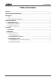
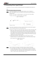
Table Of Contents

Quick Start Guide
2
1.2 Connecting Alarm Input/Output
The camera can connect to external alarm input/output device through digital input/output port.
Alarm input/output is available on select models.
Step 1 Connect alarm input device to the alarm input end of the I/O port. See Figure 1-2.
Device collects different states of alarm input port when the input signal is idling and
being grounded.
●
Device collects logic "1" when input signal is connected to +3V to +5V or idling.
●
Device collects logic "0" when input signal is grounded.
Figure 1-2 Alarm input
Step 2 Connect alarm output device to the alarm output end of the I/O port. The alarm output is
open-drain output, which works in the following modes.
●
Mode A: Level application. Alarm outputs high and low level, and the alarm outlet is OD,
which requires external pull-up resistance (10K Ohm typical) to work. The maximum
external pull-up level is 12V, maximum port current is 300 mA and the default output
signal is high-level (external pull-up voltage). The default output signal switches to low-
level when there is alarm output (As long as the operating current is below 300 mA, the
output low-level voltage is lower than 0.8V).
●
Mode B: Switch application. Alarm output is used to drive external circuit, the
maximum voltage is 12 V and the maximum current is 300mA. If the voltage is higher
than 12 V, please use an additional electric relay.
Figure 1-3 Mode A
Step 3 Log in to web page, and configure alarm input and alarm output in alarm setting.
●
The alarm input on the web ipage is corresponding to the alarm input end of the I/O
port. There will be high level and low level alarm signal generated by the alarm input
device when alarm occurs, set the input mode to "NO" (default) if the alarm input signal
is logic "0" and to "NC" if the alarm input signal is logic "1".