
User's Manual

5
4 System Structure
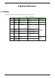
4.1 Wiring
Wiring of the device includes two groups of wires, as 8-pin and 3-pin.
Table 4-1 8-pin wires
No.
Color
Port
Note
Protocol
1
Red
12 V
12V DC
-
2
Black
GND
GND
-
3
Blue
ALARM_OUT
Wiegand Protocol
vandal proof alarm
output
Wiegand
Protocol
4
White
D1
Wiegand signal 1
5
Green
D0
Wiegand signal 0
6
Brown
LED/BELL_CTRL
Wiegand swipe card
signal
7
Yellow
RS485-
-
RS485
protocol
8
Purple
RS485+
-