
User's Manual

5
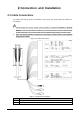
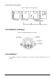
No.
Name
3
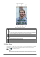
Ethernet port
4
Ethernet port (only supported by 7-inch model B access controllers)
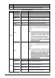
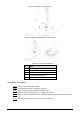
Table 2-2 Port description
Port
Cable color
Cable name
Description
CON1
Black
RD–
Negative electrode of external card reader.
Red
RD+
Positive electrode of external card reader.
Blue
CASE
Tamper alarm input of the external card reader.
White
D1
Wiegand D1 input (connected to external card
reader)/output (connected to controller).
Green
D0
Wiegand D0 input (connected to external card
reader)/output (connected to controller).
Brown
LED
Connected to external reader indicator in
Yellow
B
RS-485 negative electrode input (connected to
external card reader)/output (connected to
controller, or connected to door control security
module).
If the security module is enabled, you need
to purchase access control security module
separately. The security module needs
separate power supply to provide power.
Once the security module is enabled, the
exit button, lock control and firefighting
linkage will be invalid.
Purple
A
RS-485 positive electrode input (connected to
external card reader)/output (connected to
controller, or connected to door control security
module).
If the security module is enabled, you need
to purchase access control security module
separately. The security module needs
separate power supply to provide power.
Once the security module is enabled, the
exit button, lock control and firefighting
linkage will be invalid.
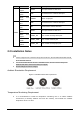
CON2
White and red
ALARM1_NO
Alarm 1 normally open output port.
White and
orange
ALARM1_COM
Alarm 1 common output port.
White and
blue
DOOR2_NO
Lock control normally open port.
White and
gray
DOOR2_COM
Lock control common port.
White and
yellow
GND
Connected to the common GND port.