
Data Sheet
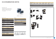
DH ultraminiature switch
∙ Dimensions only 8.2 mm × 2.7 mm × 6.2 mm
∙ Designed for low switching currents and voltages
∙ Available with or without auxiliary actuator
∙ Solder connection or use lying or standing
on a circuit board
DH ULTRAMINIATURE SWITCH
• Not every confi gurable variant is available for order. Please contact us.
• The fi nal two digits of article numbers on commercial documents refer to the
index of the respective drawing.
Technical specifi cations
Series
DH
❶
Contact confi guration S.P.D.T.
Contact gap < 3mm
Switching voltage max. 30V DC
Switching current 5 to 500mA DC
Operating voltage Max. 90cN
Total travel Approx. 0.85mm without auxiliary
actuator
Mechanical life > 50,000 operations
Electrical life
(max. load)
> 30,000 operations
Ambient temperature – 25°C to + 70°C
Materials
Housing PPS (UL 94V-0)
Cover PBT (UL 94V-0)
Auxiliary actuator PBT (UL 94V-0)
Terminals CuZn striped silver-plated
Contacts AgNi, gal. Au
Degree of protection
Switch interior
IP40
Circuitry ❸
Model Code
S.P.D.T. C
Terminal type ❹
Model Code
Solder terminal, straight, 1.3 x 3.1mm B1
PCB terminal, straight, 0.64 x 3.1mm C4
PCB terminal, RH side, 0.64 x 3.1mm C5
PCB terminal, LH side, 0.64 x 3.1mm C6
Electrical rating and operating life ❷
Electrical rating Operating life
at nominal load mechanical Code
5 – 500mA 30V DC 30,000 50,000 2
Auxiliary actuator ❺
Auxiliary actuator
Ausführung
Operating
force
max.(cN)
Max.
pretravel
(mm)
Min.
overtravel
(mm)
Diff erential
travel
max.(mm)
Max. rest
position
(mm)
Operating
point
(mm) Code
Without auxiliary
actuator
90 – 0.1 0.07 6.2 5.4
0.15 AA
With auxiliary actuator 50 – 0.3 0.6 8.5 6.7
0.5 PA
Generation of order code (example)
The order code consists of 5 parameters:
❶❷❸❹❺
Series Electrical rating Circuitry Terminal type Auxiliary actuator
DH
= Ultraminiature
switch
2
= 5 – 500mA,
30V DC
C
= S.P.D.T.
B1
= Solder terminal,
straight 1.3 x 3.1
PA
= with auxiliary
actuator
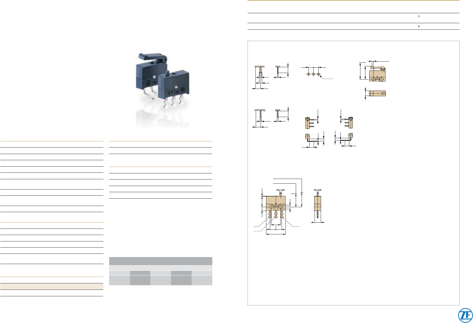
Terminals Auxiliary actuator (Plastic)
Dimensions in mm
Solder terminal
0.8 0.5
1.3
2.5
3.1
Drilling pattern
1.0
-0.1
2.52.5
1.1 ± 0.4
2.5
SP
RS
2.5
0.64 0.6
3
3.1
0.64
0.6
1.8
3.1
0.64
0.6
1.8
PCB terminal, straight PCB terminal
RH side LH side
Rest position
Operating point
COM
NO
NC
max. 6,2
1,6
1.6
4.45
0.15
0.89
0.58
2.7
2.52.5
8.2
4 ± 0.1
5,6 ± 0,2
For detailed information please note the technical specifi cations which you can fi nd in the download section of our website www.switches-sensors.zf.com.