
Data Sheet
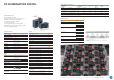

DC SUBMINIATURE SWITCH
CONTINUED
Switching parameters
Model Type Max.
operating force
(cN)
Max.
pretravel
(mm)
Min.
overtravel
(mm)
Differential
travel
max.(mm)
Max. rest
position
(mm)
Operating
point
(mm)
Length
actuator
Without auxiliary
actuator
DC1, 3, 4
DC2
200
340
1.0
1.0
0.6
0.6
0.1
0.1
9.3
9.3
8.4
0.3
8.4
0.3
–
Electrical rating at DC voltage
Please see our technical specification for DC currents (TS-0002)
which is available upon request.
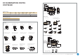
Plastic auxiliary actuator
with/without adjusting screw
Steel auxiliary actuator
max.
8,5
6.7
Rest position
min. 500max. 20
Operating point
End position
NO lead, blue
NC lead, grey
COM lead
black
Leads attached on
actuator side
Leads attached on
side opposite actuator
2.3
6.95
max. 9.3
min. 500
min. 7.7
max.
7.7
2.54
9.5 5.16
7.5
Ø 2.175
8,4 ± 0.3
Special model with tall
base available on request
»L« ± 0.8 Ø 5
»L« ± 0.8 R 2
»L« ± 0.8 Ø 4.8
»L« ± 0.8 R 2.5
»L« ± 0.8 »L« ± 0.8
SP
RS
Simulated roller
Roller
Straight
3.53.5
2.9
5.6
Straight
Roller
Simulated roller
3.53.5
3.3
≤ 5.5
Auxiliary actuator
Model with connecting leads (IP67)
7.54.85
2.54
7.5 7.5
5.16
2.73
2.35
6.7
9.5
2.3
6.95
min. 7.7
max. 9.3
max. 7.7
8.4 ± 0.3
Rest position
Operating point
End position
max. 20
Ø 2.20
6.45
Dimensions in mm
Terminals
3.35
Ø 1.875
1.35
7.3
6.7
6.7
Solder terminal short
max. 30° twisted
Q.C. terminal 2.8 x 0.5 mm
max. 30° twisted
PCB terminal 1.3 x 0.5mm
max. 30° twisted
PCB terminal 0.6 x 0.5mm
max. 30° twisted
PCB terminal 0.6 x 0.5mm
RH side w/o location pin
PCB terminal 0.6 x 0.5mm
RH side with location pin
PCB terminal 0.6 x 0.5mm
LH side w/o location pins
PCB terminal 0.6 x 0.5mm
LH side w/o location pins
Side definition with terminals
and location pins
Ø 1.6
7.5 7.5
Ø 1.3
7.5 7.5
Ø2.15
Ø 1.3
7.5
9.53
2.73
7.5
5.08
Drilling pattern for PCB
terminal 1.3 x 0.5mm
Drilling pattern for PCB
terminal 0.6 x 0.5mm,
straight/lateral
Drilling pattern for PCB terminal
0.6 x 0.5mm, lateral with
location pins
3.5
6.75
5.08
3
3.5
6.75
5.08
3.5
6.75
5.08
3
3.5
6.75
5.08
RH side
LH side
Form A Form B
Dimensions in mm
For detailed information please note the technical specifications which you can find in the download section of our website www.switches-sensors.zf.com.