
Data Sheet

D4 MINIATURE SWITCH
CONTINUED
• Not every configurable variant is available for order. Please contact us.
• The final two digits of article numbers on commercial documents refer to the
index of the respective drawing.
• Customer-specific models are marked with a G or W as the sixth digit of the
article number.
Electrical rating and operating life ❷
Electrical rating
according to***
Electrical life for 40T85*
(operations)
Mechanical lifetime
actuator material
Operating force Housing mark Code
EN/UL 61058-1 acc. to EN/UL POM PET max. (cN)
Standard operating force
0.1 (0.05) A, 250V AC 50,000 10 x 10
6
1 x 10
6
170 D4 1 Y 1
3 (1) A, 250V AC 50,000 10 x 10
6
1 x 10
6
170 D4 2 Y 2
6 (2) A, 250V AC 50,000 5 x 10
6
25 x 10
4
170 D4 3 Y 3
10 (3) A, 250V AC 50,000 1 x 10
6
1 x 10
5
285 D4 4 Y 4
16 (4) A, 250V AC 50,000 2 x 10
5
1 x 10
5
400 D4 5 Y 5
Light operating force
0.1 (0.05) A, 250V AC 50,000 10 x 10
6
1 x 10
6
45** D4 1 X 1
3 (1) A, 250V AC 50,000 10 x 10
6
1 x 10
6
45** D4 2 X 2
6 (2) A, 250V AC 50,000 10 x 10
6
5 x 10
5
45 D4 3 X 3
10 (3) A, 250V AC 50,000 10 x 10
6
25 x 10
4
75 D4 4 X 4
16 (4) A, 250V AC 50,000 10 x 10
6
25 x 10
4
100 D4 5 X 5
21 (8) A, 250V AC 10,000 3 x 10
6
25 x 10
4
150 D4 8 X 8
* Operating life 40T125 and 40T150 on request
** Lower operating forces on request
*** Additional electrical ratings according to UL 1054 on request
Switching parameters
Model Type Max. operating force (cN)
Standard Light
Max.
pre travel
(mm)
Min.
overtravel
(mm)
Differential
travel
max.(mm)
Max. rest
position
(mm)
Operating
point
(mm)
Code
Without
auxiliary
actuator
D41
D42
D43
D44
D45
D48
170
170
170
285
400
–
45
45
45
75
100
150
1.2
1.2
1.2
1.2
1.2
1.6
1.3
1.3
1.3
1.3
1.3
1.2
0.3
0.3
0.3
0.3
0.3
0.3
16.2
16.2
16.2
16.2
16.2
16.2
14.7
0.5
14.7
0.5
14.7
0.5
14.7
0.5
14.7
0.5
14.7
0.5
AA
Terminal type ❹
Terminal type Code
Q.C. terminal 6.3 x 0.8mm, straight V1
Q.C. terminal 6.3 x 0.8mm, dog leg V3
Q.C. terminal 6.3 x 0.8mm, RAST 5 Y5
Q.C. terminal RAST 2.5 X5
Q.C. terminal 4.8 x 0.8mm, straight* Q1
Q.C. terminal 4.8 x 0.8mm, dog leg* Q3
Q.C. terminal 4.8 x 0.5mm, straight** R1
Solder terminal short* B8
Solder terminal with temperature-stop S1
Welding terminal A1
PCB terminal 1.3 x 0.8mm, housing side* PA
PCB terminal 1.3 x 0.8mm, cover side* PB
PCB terminal 1.3 x 0.5mm, underside* P4
* Not for D48
** D45 and D48 not with VDE approval, only UL1054
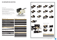
Auxiliary actuator ❺
Type Mounting
point
Length Code Code
Without auxil-
iary actuator
AA
Material Nickel-
plated steel
Optional
stainless
steel
Straight RM rear
FM front
21.2
35.6
69.9
25.7
40.1
74.4
LA
LD
LL
MA
MD
ML
JA
JD
JL
KA
KD
KL
Roller RM rear
FM front
20.6
34.1
25.1
38.6
RA
RD
TA
TD
Simulated
roller
RM rear
FM front
20.6
25.1
SA
UA
Generation of order code (example)
The order code consists of 5 parameters:
❶❷❸❹❺
Series Electrical rating Circuitry Terminal type Auxiliary actuator
D4
= Miniature
switch
5
= 16 (4) A,
250V AC
9
= S.P.D.T.
V3
= Q.C.terminal,
dog leg,
6.3 x 0.8mm
AA
= without
auxiliary actuator
Length of auxiliary actuator
Straight
Roller
Simulated roller
Rear mounting point (RM)
9
10.55
Front mounting point (FM)
13.5
Auxiliary actuator
For detailed information please note the technical specifications which you can find in the download section of our website www.switches-sensors.zf.com.