
Specifications


181
Wiring Connections to the Model 620x
•In the Station Configuration Menu of the Model 620x programming, the unit must
have its Communications Mode set for Wire Line
• The Model 620x 4-wire Receive (R107) pot should be turned all the way down (set
fully counterclockwise)
• Set jumper JP8 (2-wire RCV Impedance) each unit according to whether the
transponder is the primary or secondary unit at that station:
Primary Station Unit = set JP8 to position “A” = 600
Ω
Secondary Station Unit = set JP8 to position “B” = 3.3 kΩ
• Set jumper JP5 (FFSK Output Range) to the “TEL” position, if FFSK transmit
levels cannot be set high enough, move it to the “PWR” position and try again
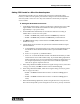
Basic 4-wire Interface
•In the Station Configuration Menu of the Model 620x programming, the unit must
have its Communications Mode set for Wire Line
• The Model 620x 2-wire Receive (R135) pot should be turned all the way down (set
fully counterclockwise)
• Set jumper JP10 (4-wire RCV Impedance) each unit according to whether the
transponder is the primary or secondary unit at that station:
Primary Station Unit = set JP10 to position “A” = 600
Ω
Secondary Station Unit = set JP10 to position “B” = 10 kΩ
4
3
11
9
1
11
9
1 2 3 4 5 6 7 8
ON
1 2 3 4 5 6 7 8
ON
SW-2
SW-1
Primary Model 6
J5
J4
J3
4
3
11
9
1
11
9
J5
J4
J3
Secondary Model 6
1 2 3 4 5 6 7 8
ON
1 2 3 4 5 6 7 8
ON
SW-2
SW-1
To 4-wire
Wireline Service
Unit Address = 5
Unit Address = 517
TX Pair
PA Audio ComB
TX & 2W RX Audio & FFSK
TX & 2W RX Audio & FFSK
4W RX Audio & FFSK
4W RX Audio & FFSK
PA Busy
PA Audio ComA
PA
Basic 4-wire System
RX Pair