
Specifications


Appendix C: Using a Model 620x in a Model 26-based System
180 025-9581M
•In the Station Configuration Menu of the Model 620x programming, the unit must
have its Communications Mode set for Trunked with the appropriate polarity for
channel grant.
• Set jumper JP5 (FFSK Output Range) to the “RAD” position, if FFSK transmit
levels cannot be set high enough, move it to the “TEL” position and try again
Connections to Wire-line
The material shown in the following sub topics is taken from the Model 6 manual.
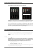
Basic 2-wire Interface
M6 Connection Description
J4-pin 7 Ground
J4-pin 8 PTT
J4-pin 9 TX Audio -
J4-pin 11 TX Audio +
J5-pin 1 COR (Channel Grant)
J5-pin 3 RX Audio +
J5-pin 4 RX Audio -
11
9
1
11
9
1 2 3 4 5 6 7 8
ON
1 2 3 4 5 6 7 8
ON
SW-2
SW-1
Primary Model 6
J4
J3
11
9
1
11
9
J4
J3
Secondary Model 6
1 2 3 4 5 6 7 8
ON
1 2 3 4 5 6 7 8
ON
SW-2
SW-1
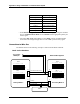
To a wireline
TX/RX pair
Unit Address = 5
Unit Address = 517
PA Audio ComB
TX & 2W RX Audio & FFSK
TX & 2W RX Audio & FFSK
PA Busy
PA Audio ComA
PA
Basic 2-Wire System