
Specifications


Appendix A: Details of Model 6203/6204 Hardware
154 025-9581M
Connector J6 (IP Interface Connection)
This connector is a serial port. It is connected to the serial output connector on the IP
Interface board. The part number for the connecting cable is 702-7856. Jumper 11 must be
in the “9600” position. Jumper JP-12 should be in position “A”.
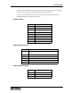
Table 8: J6 Serial Port Pinout
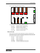
Power Supply Board Connectors
There are four types of electrical connections to the Power Supply board: relay outputs,
relay control, power input (12 Vdc), and sense inputs. Figure 51 shows the relative
locations of the connectors on the Power Supply board.
Relay Connections (P1-P4)
P1 - P4 are made through four general purpose, 2 A, DPDT relays that can be used for a
wide variety of control applications. Connector P1 is associated with relay 1, P2 with relay
2, P3 with relay 3, and P4 with relay 4. Each of these relays is controlled by the dispatcher
via the FSA Console user interface. They can also be locally controlled by either a switch
connected to the P9 connector (to be discussed), or by an event such as an alert at the
Model 6203 (programmable). The way in which these relays are controlled is user
configurable (please see Station I/O Settings on page 92). Each relay has two sets of Form
C contacts, set “A” and set “B”. There are four LEDs (DS1 through DS4) that monitor the
state of their respective relays. When they are on, their associated relay is activated.
Pin Description
Pin 1 This pin is not connected.
Pin 2 (RXD) This pin is RXD if JP-12 is in position “A”. There is no connection oth-
erwise.
Pin 3(TXD) Data output
Pin 4 (RXD/DTR) This pin is DTR when JP-12 is in position “A”. It is pulled up to +12V
through 4.7K. This pin is RXD if JP-12 is in position “B”.
Pin 5 (GND) This pin is connected to the Model 6203 chassis ground.
Pin 6 This pin is not connected.
Pin 7 (RTS) RTS Output
Pin 8 (CTS) CTS input, this pin is pulled up to +12V through 10K.
Pins 9 This pin is not connected.