
Specifications


Using a Model 26 Fire Station Dispatcher for System Backup
138 025-9581M
Model 26 Backup in a VoIP System
The assumption made in writing these procedures is that the system is already up and
running as a VoIP system or, at the very least, planned and laid out to operate in that
manner. The Model 26 as a backup is being added to that system. The procedures in this
section are presented in the following order:
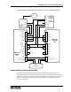
• Connections between the Model 6203 units and the radio transceiver, please
refer to Figure 48
• Jumper changes inside the Model 6203 units
• Programming changes to the Model 6203 units
• Level setting procedures to ensure proper FFSK levels
In order for the station units to switch between IP-mode and FFSK-mode without operator
action, the COR input will be tied low and the units shifted to VOX mode operation (if
they were not already set to that). If the station has both a Model 6203 and a Model 6204,
both units must share the RX audio, TX audio, and PTT line. This is because, in FFSK-
mode operation, each of the station units individually must be able to exchange FFSK
packets with the Model 26.
Connection between the Station Alerting Units and the Radio
The following procedure establishes the connections between the station alerting units and
the radio transceiver to allow the system to operate in both modes: IP network-based and
FFSK packet-based. If the station being worked on does not have a Model 6204 installed,
you may simply ignore any of the connections indicated for a Model 6204. Refer to Figure
48 for overall wring connections.
♦ Connecting the Model 6203 to the radio for voice and FFSK backup:
1. If any wire is connected to the PTT Out (P4, pin 1) signal of the IP Interface
Board, disconnect it.
2. Jumper the RX COR input (J5, pin 1) on the station unit to ground (J5, Pin 2).
The COR output of the radio should not be connected to anything.
3. Connect the RX audio from the radio to RX Audio + (J5, pin 3) on the station unit
motherboard. Connect the RX Audio - (J5, pin 4) to ground (J5, pin 2).
4. Connect the TX audio input of the radio to TX Audio + (J4, pin 11) on the station
unit motherboard. Connect the TX Audio - (J4, pin 9) to ground (J4, pin 7).
5. Connect the XMIT PTT output (J4, pin 8) of the station unit to the PTT input of
the radio.
6. Review all of your connections to ensure that they have been made to the correct
pins and that they are securely fastened.