
Specifications


113
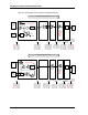
Connections to the Station Transponder Unit
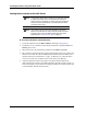
Figure 41: Typical PA Audio Connections in a System Using VoIP
Front Panel Test Mode
If the top left and top right buttons are both pressed and held while power is connected to
the unit, the Model 6203 enters a test mode. The Test Mode is indicated by the state of the
LEDs in the fourth row down from the top (ON SCENE). When the Model 6203 is in test
mode, these LEDs are on at start-up. The test mode can be used to test the following:
• Relays
• Sense Inputs
•Buttons
• LEDs
This mode of operation is brought up here because being able to manually cycle relays or
check the status of sense inputs might come in very handy while you are wiring up I/O
connections to the relays and sense inputs.
Connections on
IP Interface
Board
Model 6203
IP Station Unit
Model 6204
IP Station Unit
AUX RX "A"
AUX RX "B"
RX COR
TX Audio +
TX Audio -
PA Busy
PA Audio Comm A
PA Audio
Comm B
RX COR
GND
GND
1
2
J5
11
9
7
4
3
2
J4
GND
PA Audio Comm A
PA Audio
Comm B
1
11
9
J3
1
11
9
J3
Common
PA System
Input 2Input 1
RX
Audio
TX
Audio
PTT
In
P4
543
GND
4
3
2
J4
GND
AUX RX "B"
AUX RX "A"
8
7
2
1
J5
Handset
PTT
HKSW
Off
Hook
2
6
IP
Network
GND