
Instruction manual


Installation
72 025-9416
Glenayre Transmitter Interface
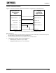
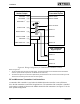
Figure 35 illustrates a direct connection to a colocated Glenayre transmitter. The Glenayre pin
numbers refer to the backplane terminal block connector (TB1).
Model 640 RJ21
Radio Station Output
Glenayre Paging
Transmitter Signal
Inputs (TB1)
XMIT AUDIO LO (40) (2) LINE IN +
AUX PTT NO (23) (7) TX IN
XMIT AUDIO HI (15) (1) LINE IN -
AUX PTT COM (24)
GROUND (17) (8) GROUND
Data Input (DB-25)
(7) GROUND
(18) CD
DIG DATA (42) (5) RTS
DIG MODE (14) (3) DATA IN
Figure 35. Wiring Configuration for Colocated Glenayre Transmitter
Notes on Figure 35:
The following parameter settings are typical for connection to a Glenayre transmitter. In the Model 640 Transmitter
Key Up Control database:
• Set the ModeSgnlPlrty parameter to “high” for digital.
• If the transmitter keys, but the digital pagers do not alert, try setting the DigDataPolarity parameter to “0”.
Quintron 1000 Exciter Interface
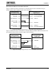
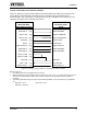
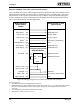
Figure 36 illustrates a typical cable hookup between the Model 640 radio station interface and a
Quintron 1000 Exciter.
Model 640 RJ21
Radio Station Output
Paging Exciter
Signal Inputs
DIG MODE (14) Mode Select
XMIT AUDIO HI (15) Flat
AUX PTT NO (23) Key In
XMIT AUDIO LO (40) Flat
DIG DATA (42) Data
AUX PTT COM (24)
GROUND (17) GROUND
Figure 36. Wiring Configuration for Quintron 1000 Exciter