
Instruction manual


Installation
025-9416 63
Follow the steps below to interface the terminal block adapter to the radio station equipment:
q
1. Power-down the paging terminal.
q
2. Obtain or make cabling for either one or both radio station connections (P1 - analog,
P2 - digital). Both interfaces require male 12-pin Wiedmueller connectors on the
Model 640 end.
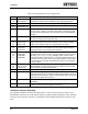
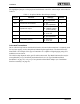
3. Table 10 shows the pin configuration of each interface. Also, refer to Table 9 for
descriptions of each signal and its application.
Table 10. Terminal Block Adapter Radio Station Wiring Configuration
Pin # P1: Radio Analog P2: Radio Digital
1 GND GND
2 Tx Audio Low Terminal Busy
3 Tx Audio High Zone BCD Bit 1
4 COR Zone BCD Bit 2
5 Analog PTT - NO Zone BCD Bit 4
6 Analog PTT - COM Zone BCD Bit 8
7 Analog PTT - NC Digital PTT - NO
8 AUX PTT - NO Digital PTT - COM
9 AUX PTT - COM Digital PTT - NC
10 AUX PTT - NC Digital Mode
11 Rx Audio Low Request Transmit
12 Rx Audio High Digital Data
q
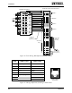
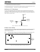
3. Install a cylindrical ferrite (Part No. 305-0735) over each half of the Model 640 end
of the split cabling as shown in Figure 27. Two ferrites are supplied with the
installation interface assembly option for suppressing RF noise interference.
q
4. Use the included cable ties (Part No. 265-0001) to secure the individual wires
together at the ends and in the middle of each half of the cabling, as shown in the
illustration above.
q
5. Attach an appropriate connector to the other end of the cabling for the radio station
interface. The type of connector is governed by the specific equipment used. Refer
to “RF EQUIPMENT INTERFACING” on page 66 for details on many of the
possible transmitter equipment interfaces.