
Instruction manual


Installation
025-9416 57
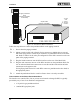
Telco Punchdown Block Interface
The block typically has telco wiring on one side and open terminals on the other side. To inter-
face the phone company’s punchdown block to the Model 640, a second punchdown block is
usually required to split the radio station and trunk wiring out of the RJ21 connector (already
installed above).
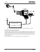
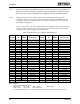
Figure 23 illustrates the hardware connections between a common telco 66-type punchdown
block and the Zetron punchdown block. The block provides eight trunks, although the Model 640
only uses a maximum of four trunks. Notice that the telco line type in the figure is 4-wire E&M.
R
J
2
1
R
J
2
1
26
1
27
2
28
3
29
4
30
5
31
6
32
7
33
8
34
9
35
10
36
11
37
12
38
13
39
14
40
15
41
16
42
17
43
18
44
19
45
20
46
21
47
22
48
23
49
24
50
25
T1
R1
T2
R2
E
M
T1
R1
T2
R2
E
M
T1
R1
T2
R2
E
M
T1
R1
T2
R2
E
M
G
G
R
J
2
1
26
1
27
2
28
3
29
4
30
5
31
6
32
7
33
8
34
9
35
10
36
11
37
12
38
13
39
14
40
15
41
16
42
17
43
18
44
19
45
20
46
21
47
22
48
23
49
24
50
25
T1
R1
T2
R2
E
M
T1
R1
T2
R2
E
M
T1
R1
T2
R2
E
M
T1
R1
T2
R2
E
M
T1
R1
T2
R2
E
M
T1
R1
T2
R2
E
M
T1
R1
T2
R2
E
M
T1
R1
T2
R2
E
M
G
G
radio station
wiring
25-pair cable
(Part No.
709-0004)
To Model 640
RJ21 interface
(See Figure 5-6)
To telco
interface
TRUNK A
TRUNK B
TRUNK C
TRUNK D
Telco Punchdown Block (4-wire E & M) Model 640 Interface Punchdown Block
bridging
clips
standard 26
gauge
telephone wire
Figure 23. E&M 4-Wire Telco Interface
Follow the steps below to interface to the telco punchdown block:
q
1. Power-down the paging terminal.