
Instruction manual


Installation
025-9416 55
To telco
connection
To Model 640
terminal block
adapter
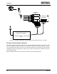
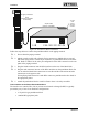
Figure 21. Clamp-On Ferrite (Part No. 305-2025) Installation
CAUTION
Four clamp-on ferrites (Part No. 305-2025) are supplied with the optional terminal
block adapter kit. The ferrites must be installed on each phone cord, immediately
adjacent to the Model 640 chassis.
Failure to properly install the ferrites may result in radio interference!
q
4. Plug a cord into each of the telco jacks on the terminal block adapter.
q
5. Connect the other end of each cord to the telephone line.
Telco connections for the optional installation interface assembly are complete. Proceed to
“RADIO STATION CONNECTIONS” on page 61.
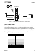
66-Type Punchdown Block Installation
Zetron offers two versions of the 66-type punchdown block for installation of the Model 640.
The most flexible punchdown block (Part No. 802-0093) provides 50 terminals and a female
RJ21 25-pair connector jack on either side of the block. The other punchdown block (Part No.
802-0263) provides only one RJ21 jack and has an easy-to-spot orange cover. Both blocks can be
used for any type of connections, but each has advantages for specific applications.
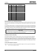
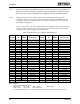
Both punchdown blocks are configured with 50 rows (each corresponding to a pin) and four
columns (terminals per row). The two left terminals in each row are electrically identical, as are
the two right terminals. Paired bridging clips and fused bridging clips are available from other
vendors to connect the two sides of the punchdown block.
Punchdown Block Installation
Zetron recommends using a female-to-male 25-pair cable (Part No. 709-0004) and a 66-type
punchdown block (Part No. 802-0093) to interface the Model 640 to both the telco and the radio
station.
Figure 22 illustrates the hardware connections between the Model 640 and the punchdown block.