
Instruction manual


Optional Equipment Installation
108 025-9416
DIAL CLICK DECODER
The dual dial click decoder option (Part No. 702-9119) enables the terminal to process numbers
dialed by rotary telephones. Dial clicks are distinctly different from dial pulses. The Model 640
decodes dial pulses without the optional dual dial click decoder board.
Installation
To install this option onto a dual trunk card (Part No. 702-9361 or 702-9488) of the Model 640,
proceed as follows:
CAUTION
Please exercise electro-static discharge (ESD) precautions when handling all parts.
q
1. Power-down the paging terminal.
q
2. Remove the top cover.
q
3. Unscrew the card guide from the back of the chassis for the dual trunk that the dial
click decoder is to be installed onto. Pull the dual trunk from its connectors.
q
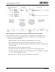
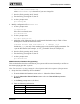
4. Mount the supplied standoff near the center of the board as shown in Figure 58.
J5
P2
P1
standoff
mount
Dial Click Board
(Part No. 702-9119)
Dual Trunk Card
(Part No. 702-9361)
Figure 58. Dial Click Board Installation
q
5. Install the dual dial click board into the 10-pin female connector (J5) on the dual
trunk. The card should extend toward the rear of the dual trunk board. Bolt the board
to the standoff installed in Step 4.
q
6. Plug the supplied extender card into the connectors on the paging terminal peripheral
board where the dual trunk was installed. Then plug the dual trunk into the extender
card. This enables easy access to the dial click pots for adjustment.
Note: If an extender card is not available and trunk A or B needs adjustment, remove the
other dual trunk card (C/D) to perform the procedure.