
Instruction manual


Optional Equipment Installation
025-9416 97
OPTIONAL EQUIPMENT INSTALLATION
This section provides installation instructions for several hardware options that may need to be
field-installed (upgrades after initial installation). These procedures can also be used to identify
where the optional cards are installed in the factory-configured system and how they are
connected to the rest of the Model 640 processor boards.
DUAL TRUNK CARD
A standard Model 640 comes equipped with one dual trunk interface (Part No. 702-9361) card.
The unit can be upgraded to support a second dual trunk card, bringing the total number of trunks
up to four (two per card).
Either one or both of the trunk cards may be optional, dual-trunk, 4-wire, audio cards (Part No.
702-9488) for 4-wire audio circuits (for example, E&M, 4-wire RF/µwave links, T1 trunks, etc.)
Follow the steps below to install either type of dual trunk card:
q
1. Power-down the paging terminal.
q
2. Remove the top cover.
q
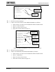
3. Verify that the matrix cards are configured for the appropriate line types. The matrix
plug in J3 defines trunk C and J4 defines trunk D. See “Line Type Matrix Card” in
Section 3 for details on the matrix card settings.
q
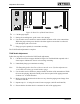
4. Plug the dual trunk into the left connectors (J2 and J4) on the peripheral board.
Again, refer to Section 3 for illustrations of the dual trunk and its placement in the
Model 640 chassis.
q
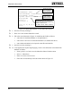
5. Secure the card guide to the top of the back panel with the provided screw.
q
6. Power-up the unit and let it complete its boot sequence (all lights have extinguished,
except the READY LED is on solid).
q
7. Access the Model 640 database and edit the Trunks database to configure trunks C
and D. Refer to the Model 640 Operating and Programming Manual (Part No. 025-
9417) for details on how to edit these databases.
q
8. After the databases have been setup, reboot the Model 640 to initialize the changes.
q
9. Refer to Section 6 for detailed adjustment procedures and level settings.