
Instruction manual


INSTRUCTION MANUAL - Issue 1 - 07/2014 | 9
CHANNEL SAFETY SYSTEMS t: 0845 884 7000 | w: www.channelsafety.co.uk
Panel Relays
The panel is equipped with four programmable relays, each capable of supplying 500mA. The total current draw
across all four relays must not exceed 1A. The default relay types are:
Relay 1: Fire Routing Relay - This activates on an alarm condition. It switches 12V onto the output and is moni-
tored for short and open circuit, with a 4K7 EOL. The circuit should be connected between the C and the NO
terminals. The fuse should be tted and the links put in the lower position.
Relay 2: Fault Failsafe Relay - This energises on power-up and de-energises in fault. Consequently the normally
open and normally closed terminals are reversed. The fuse should be removed and the links tted in the upper
position as shown on the PCB layout diagram.
Relays 3 & 4: Sounder Circuits - These are each capable of supplying 500mA at 12V. Both the sounder circuit fuses
should be tted in the fuse holders and the links tted in the left or lower positions as shown on the PCB layout
diagram. The circuit should be connected between the S+ and the S- terminals. A 4K7 end of line resistor should
be tted to monitor the circuit.
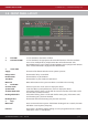
The relays can be con gured as sounder circuits, monitored outputs or volt free clean contact relays. The relay type
can be changed in 6.8 – User Options and by positioning the jumper links and fuses as detailed below. When relays
are con gured as re routing or as sounder circuits, the associated terminal pin (V+) must not be used. Only the
default relay types have been type approved.
Relay Type Normal State Contacts in Alarm Fuse EOL Link Position
1. Fire Relay Not energised Clean contact None None Up/Right
2. Fault Relay Not energised Clean contact None None Up/Right
3. Sounder Circuit -4.5V 500mA +15V 500mA 500mA 4K7 Down/Left
4. Fault Relay Safe Energised Clean contact None None Up/Right
5. Fire Routing Relay -4.5V 500mA +15V 500mA 500mA 4K7 Down/Left
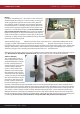
Display Cable
A ribbon cable connects the two panel boards together. It should be connected to the system link/bus
connections on the boards. Do not remove or connect the ribbon cable while the panel is powered up, as damage
can occur to the processor board.
Buzzer Link
The buzzer can be disabled by removing the buzzer link (see page 6 – PCB Layout). Note that when the buzzer is
disabled, the system will not comply with EN54.
Memory Card
The memory card stores a complete set of the system settings including device/zone text and options. The
memory card should be tted at all times unless instructed by the panel (i.e. when adding a repeater panel).
USB Socket
The USB socket can be used for connecting a keyboard to program device text. It is also used to plug in a memory
stick to download the event log, device info and the verify table so a hardcopy can be retained for records.