
Instruction manual


INSTRUCTION MANUAL - Issue 1 - 07/2014 | 8
CHANNEL SAFETY SYSTEMS t: 0845 884 7000 | w: www.channelsafety.co.uk
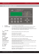
PCB Layout
Monitored Inputs
The panel features two monitored inputs that can be programmed either as latching or non-latching. It is impor-
tant to note that before using these inputs they must be enabled by programming them in the panel options
menu. If the inputs are enabled then 4K7 end of line resistors must be tted at the termination. Applying a 470
resistor across the inputs will produce a ‘Fire’ message. The inputs are labelled ‘INPUTS’ and ‘No1’ and ‘No2’. These
inputs can be assigned a zone and text location, and then cause and e ects can be programmed for them. See
6.15 – Input Options for further information.
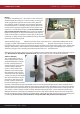
RS-485 Connections
The RS485 connectors are used for wiring hardware to the panel such as extra antennas or a secondary display. A
suitable data cable should be used with 2 sets of twisted pairs. Cat 5/5e/6 can be used but is not re rated. Wired
antennas and displays have two RS485 connectors, making it possible to make a chain of up to 4 units. On the last
unit in any chain, a 100R resistor should be tted across the D- and D+ terminals of the unused RS485 connection.
If one of the control/booster panel RS485 ports is unused then a 100R should be tted between D- and D+. If none
of the panel RS485 ports are used then there is no need to t the 100R resistor. The RS485 ports are capable of sup-
plying 500mA at 15V.
The use of this facility is not permitted for an EN54-2 compliant system.