
Instruction manual


INSTRUCTION MANUAL - Issue 1 - 07/2014 | 7
CHANNEL SAFETY SYSTEMS t: 0845 884 7000 | w: www.channelsafety.co.uk
Battery
In order to meet EN54 Part 4, a Yuasa NP7-12 lead acid battery
should be tted. This will give a 72 hour standby, assuming no
external equipment (eg wired antennas) has been added. If
only 24 hours standby is required and no external equipment
has been tted then a 12V 2.8Ahr battery could be tted. Con-
nect the battery using the supplied terminal connections. The
red wire is +12V and the black wire is 0V. Do not confuse the
colour of the terminal connectors. Once connected, the Reset
button on the keypad can be pressed. If ‘Battery Fault’ appears;
check the connections and polarity. If the battery is connected
incorrectly it is likely that the fuse will blow. The wiring should be
corrected and the fuse replaced.
The PSU will only charge batteries measuring 10.5V and above. This is a requirement of EN54-4 to cut o
charging at a point recommended by the battery manufacturer. Batteries measuring less than 10.5V are
regarded by the system as faulty and will not be charged. A ‘Battery Fault’ will be displayed on screen. If the battery
voltage is below 10.5V it will need to be removed from the panel to be charged and reconditioned, or replaced.
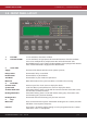
The battery voltage can be viewed on the PSU Info section of the 6.5 – Panel Info menu.
When replacing the battery always do so with a product of equal speci cation. Always dispose of batteries respon-
sibly. Never dispose of batteries in general waste. If unsure contact your local authority for guidance.
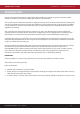
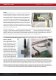
Antenna (if tted)
The standard helical stub an-
tenna supplied with the panel
should be tted to the antenna
bracket assembly before it is
mounted into the panel. Fit the
antenna onto the SMA con-
nector as shown below. This
should be screwed hand tight.
Over tightening will cause the
antenna to break. The supplied
antenna retaining washer should
then be placed over the top of
the antenna. The antenna and
bracket assembly should then
be inserted through the antenna
aperture and mounted using the supplied M3 screw and an M3 serrated locking washer. Once mounted, the an-
tenna retaining washer prevents the stub antenna being unscrewed from outside the panel. Connect the antenna
assembly to the main processor board using the SMA connector. If a high gain remote antenna is being used, the
stub antenna and the antenna bracket assembly should be removed. The new antenna should be tted using a
50 SMA connector, suitable for use with RG58 c/u coaxial cable, to the processor board. Cable runs should con-
form to the relevant sections of BS5839 and EN54. When making o the cable, ensure that no stray shielding wires
are shorting. Do not use non-radio connectors as they will reduce the performance of the panel.