
Instruction manual


INSTRUCTION MANUAL - Issue 1 - 07/2014 | 6
CHANNEL SAFETY SYSTEMS t: 0845 884 7000 | w: www.channelsafety.co.uk
The electronic components within the panel are vulnerable to electrostatic discharges. It is advisable to wear a
wrist strap designed to prevent the build-up of static charges within the body before handing any
electronic components. Do not remove or unplug any components while the panel is powered up.
Mounting
The panel should be mounted on a wall in a suitable position as recommended by BS5839 Part 1. If tted, the
antenna should be away from any solid objects, especially electronic equipment and metal structures. The wall
should be even, clean and dry and not prone to vibration. Should the wall not be level, the panel should be
mounted on a wooden board. The temperature should be in the range of -5C to +35C and the humidity should
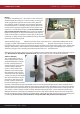
not exceed 95%. Mount the panel using 3 x No. 10 screws of a suitable
length, and ensure washers (supplied) are used to meet the IP30 rating.
The smaller washer (25mm diameter) is to be used for the mounting
hole next to the PSU.
Cabling
A 230V AC 50Hz supply capable of providing 500mA with a minimum
diameter of 7mm and a maximum diameter of 10.5mm should be
derived from a separate fused spur. This spur should not incorporate a
switch and should be labelled ‘Fire Alarm Equipment – Do Not Switch
O ’. A cable conforming to BS5839, with a core cable size no greater
than 2.5mm2 should be used. Always ensure that the mains supply is
completely isolated before working on any mains rated components.
Cables should only enter the panel housing through the knockouts provided. Do not remove more knockouts than
is needed to terminate the cables, as additional apertures in the panel will compromise the ingress protection
requirements of EN54-2/4. A nylon M20 IP66 cable gland should be used. The cable should be connected to the
terminal block as labelled from above with the Live (brown) connected to the top terminal, the Earth (green/yel-
low) to the middle and the Neutral (blue) to the bottom. Care should be taken to ensure no loose strands protrude
from the terminal block and that the wire insulation is trimmed to the correct length so that no exposed wire is left
visible. Any earth cables should not be removed.
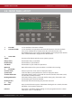
Once the connection has been made, the panel fuse (3.15A ceramic T type) should be removed from the panel by
pulling on the fuse holder. The fused spur can then be energised. To power up the panel, insert the fuse holder
with the correct value of fuse tted. As there is a high inrush current there is likely to be a spark produced. This
is normal. Mains power should always be applied prior to connecting the standby battery. Once the mains
supply has been applied, the green LED on the bottom edge of the processor board should begin to ash once a
second. The system normal screen will be displayed.
Connections to the panel inputs should be made using reproof 2 core cable with a core diameter of 1.0mm2.
A nylon M20 IP66 cable gland should be used. The Fire Routing & Sounder circuits should be connected using a
reproof 2 core cable conforming to BS5839. A suitable core diameter should be used depending on the loading of
the circuit. The Panel has been type approved to IP rating IP30.
2.0 - INSTALLATION