
Instruction manual


INSTRUCTION MANUAL - Issue 1 - 07/2014 | 17
CHANNEL SAFETY SYSTEMS t: 0845 884 7000 | w: www.channelsafety.co.uk
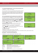
Panel Readings – service and commissioning users
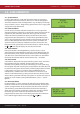
1.Main Menu>>1.Setup>>4.System Setup>>1.Panel Info>>2.Panel Readings
IP1: The resistance level on input 1.
IP2: The resistance level on input 2.
OP1: The resistance level on output 1.
OP2: The resistance level on output 2.
OP3: The resistance level on output 3.
OP4: The resistance level on output 4.
Vbus: The voltage of the PSU.
Light: Light sensor voltage.
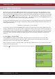
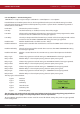
View Antenna Information –service and commissioning users
1.Main Menu>>1.Setup>>4.System Setup>>1.Panel Info>>3.Antenna Info
Ant: The currently selected antenna.
Sys: The system number programmed at the antenna.
RSSI: Received signal strength indicator, from -20 to +20.
RF Chan: The channel the system is using.
Pan: The number of the panel programmed at the antenna.
Slot: Device protocol slot.
Squelch: RF interference lter. Non-user adjustable.
View Pager Information – service and commissioning users
1.Main Menu>>1.Setup>>4.System Setup>>1.Panel Info>>4.Pager Info
This menu displays information for any alert pagers that have been set up on the system.
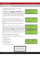
View Power Supply Information – service and commissioning users
1.Main Menu>>1.Setup>>4.System Setup>>1.Panel Info>>5.PSU Info
Vin: Input Voltage.
Vbus: The voltage of the PSU.
Vbat: The voltage of the battery.
Ib: Battery current.
Io: PSU output current.
Status: PSU fault status.
State: PSU state.
PWM: Duty cycle.
Temp: PSU temperature (oC).
Version: The rmware version of the power supply PCB.
Uptime: Operational time since PSU was last powered down.