
Instruction manual


INSTRUCTION MANUAL - Issue 1 - 07/2014 | 10
CHANNEL SAFETY SYSTEMS t: 0845 884 7000 | w: www.channelsafety.co.uk
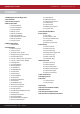
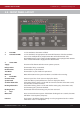
3.0 - FRONT PANEL LAYOUT
1. Fire LEDs In a re condition, these LEDs will ash.
2. Zone Alarm LEDs In a re condition, the appropriate zone LED will illuminate. If the re condition
exists across multiple zones, multiple zone LEDs will be illuminated. *The
EDA-Z5008 8 Zone panel is shown. The EDA-Z5020 panel is equipped with 20 zone
LEDs and the EDA-Z5100 is equipped with 100 zone LEDs
3. Status LEDs
Supply This LED will be illuminated when mains power is present.
Delays Active Illuminated if delays are enabled.
Disablements Illuminated for any disablement.
Test Mode Illuminated if any test modes are operational.
More Info More information on the system condition is available in the event log.
4. Fault LEDs
Common Fault Device or panel has a fault. See main display for details.
System Fault Fault that a ects system performance. See main display for details.
Sounder Flt/Disable If the LED is ashing, there is a fault with one or more sounders. If the LED is solid,
the sounders have been disabled.
Routing Flt/Disable If the LED is ashing, there is a fault with the re routing relay. If the LED is solid,
the re routing relay has been disabled.
Routing Active Illuminated when the re routing relay has been activated
5. Keys
Menu/Info Press to initiate the menu system. If held down for longer than 2 seconds, the LEDs
will follow a test sequence (lamp test).
Function This button is disabled by default, though it can be programmed to do a number
of functions. See 6.8 – User Options.
1.
2.
3. 4.
6.
5.