Zerio Plus Wireless system from Channel Safety Systems CHANNEL SAFETY SYSTEMS Petersfield Business Park Bedford Road Petersfield Hampshire GU32 3QA t: 0845 884 7000 f: 0845 884 6000 e: sales@channelsafety.co.uk w: www.channelsafety.co.
CHANNEL SAFETY SYSTEMS t: 0845 884 7000 | w: www.channelsafety.co.uk INTRODUCTION Zerio Plus has been designed to be capable of handling 240 devices in 100 zones. Typical installations would include small offices, private houses, HMO’s, guest houses and small hotels. This manual contains information to enable an engineer to install, service and operate the Zerio Plus control panel and the range of Zerio Plus devices.
CHANNEL SAFETY SYSTEMS t: 0845 884 7000 | w: www.channelsafety.co.
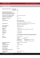
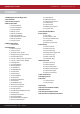
CHANNEL SAFETY SYSTEMS t: 0845 884 7000 | w: www.channelsafety.co.uk CONTENTS 1.0 EN54 Approved Configuration 2.0 Installation 3.0 Front Panel Layout 4.0 User Operation 4.1 System Normal 4.2 Fault Conditions 4.3 Silence Buzzer 4.4 Reset a Fault 4.5 Alarm Conditions 4.6 Silence the Alarm 4.7 Re-sound the Sounders 4.8 Reset the Alarm 4.9 Access Levels 5.0 Menu Operation 5.1 Quick Menu 6.0 Setup Menu 6.1 Time and Date 6.2 Access Codes 6.3 Default Access Codes 6.4 Programming Agent Details 6.
CHANNEL SAFETY SYSTEMS t: 0845 884 7000 | w: www.channelsafety.co.uk 1.0 - EN54 APPROVED CONFIGURATION The Zerio Plus system has been approved by Intertek to meet EN54 parts 2 and 4. The panels were tested and approved in their default configuration. This manual lists all available panel options and settings, some of which can be set in a way that would result in a system that does not comply with EN54.
CHANNEL SAFETY SYSTEMS t: 0845 884 7000 | w: www.channelsafety.co.uk 2.0 - INSTALLATION The electronic components within the panel are vulnerable to electrostatic discharges. It is advisable to wear a wrist strap designed to prevent the build-up of static charges within the body before handing any electronic components. Do not remove or unplug any components while the panel is powered up. Mounting The panel should be mounted on a wall in a suitable position as recommended by BS5839 Part 1.
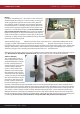
CHANNEL SAFETY SYSTEMS t: 0845 884 7000 | w: www.channelsafety.co.uk Battery In order to meet EN54 Part 4, a Yuasa NP7-12 lead acid battery should be fitted. This will give a 72 hour standby, assuming no external equipment (eg wired antennas) has been added. If only 24 hours standby is required and no external equipment has been fitted then a 12V 2.8Ahr battery could be fitted. Connect the battery using the supplied terminal connections. The red wire is +12V and the black wire is 0V.
CHANNEL SAFETY SYSTEMS t: 0845 884 7000 | w: www.channelsafety.co.uk PCB Layout Monitored Inputs The panel features two monitored inputs that can be programmed either as latching or non-latching. It is important to note that before using these inputs they must be enabled by programming them in the panel options menu. If the inputs are enabled then 4K7Ω end of line resistors must be fitted at the termination. Applying a 470Ω resistor across the inputs will produce a ‘Fire’ message.
CHANNEL SAFETY SYSTEMS t: 0845 884 7000 | w: www.channelsafety.co.uk Panel Relays The panel is equipped with four programmable relays, each capable of supplying 500mA. The total current draw across all four relays must not exceed 1A. The default relay types are: Relay 1: Fire Routing Relay - This activates on an alarm condition. It switches 12V onto the output and is monitored for short and open circuit, with a 4K7Ω EOL. The circuit should be connected between the C and the NO terminals.
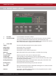
CHANNEL SAFETY SYSTEMS t: 0845 884 7000 | w: www.channelsafety.co.uk 3.0 - FRONT PANEL LAYOUT 1. 2. 3. 5. 4. 6. 1. Fire LEDs In a fire condition, these LEDs will flash. 2. Zone Alarm LEDs In a fire condition, the appropriate zone LED will illuminate. If the fire condition exists across multiple zones, multiple zone LEDs will be illuminated. *The EDA-Z5008 8 Zone panel is shown. The EDA-Z5020 panel is equipped with 20 zone LEDs and the EDA-Z5100 is equipped with 100 zone LEDs 3.
CHANNEL SAFETY SYSTEMS t: 0845 884 7000 | w: www.channelsafety.co.uk Cancel Used to return to the main screen from a menu or to return to the menu from a programming screen. Enter This is used to accept information programmed into the panel. Re-sound Alarm Following an alarm condition that has been silenced, this button will re- sound the alarm. Silence Alarm If the panel is in a fire condition this will silence the sounders.
CHANNEL SAFETY SYSTEMS t: 0845 884 7000 | w: www.channelsafety.co.uk 3.0 - USER OPERATION 4.1 - System Normal In normal operation the screen will show either the date and time, or the supplier/service contact details. The unit can also be configured to alternate between the two. If configured this way, the display will change every 4 seconds. See 6.4 – Programming Agent Details. Also a single green ‘Supply’ LED will be illuminated. 4.
CHANNEL SAFETY SYSTEMS t: 0845 884 7000 | w: www.channelsafety.co.uk 4.6 - Silence the Alarm When it is certain that it is safe to return to the building the Silence Alarm button should be pressed. The user will then be prompted to enter a valid user access code using the navigation keys. Up to 30 seconds should then be allowed for all sounders to silence. If a device is still in an alarm condition the sounders will not sound again unless another device goes into alarm.
CHANNEL SAFETY SYSTEMS t: 0845 884 7000 | w: www.channelsafety.co.uk 5.0 - MENU OPERATION To enter the menu system, press Menu. This will display an overview of any alarms, faults, disablements or tests that are currently active, along with an option to access the Main Menu. The options available on the main menu and sub-menus will be dependent on the access code entered and its corresponding access level. To scroll through the menu the and keys should be pressed.
CHANNEL SAFETY SYSTEMS t: 0845 884 7000 | w: www.channelsafety.co.uk 6.0 - SETUP MENU 6.1 - Changing the system Time and Date – all access levels 1.Main Menu>>1.Setup>>1.Time & Date To change the time and date settings use the and keys to navigate to the value, and the or keys to select the desired value. Press Enter to accept or Cancel to exit. The Zerio Plus panel automatically adjusts the clock for daylight savings.
CHANNEL SAFETY SYSTEMS t: 0845 884 7000 | w: www.channelsafety.co.uk 6.4 - Programming Agent Details – service and commissioning users 1.Main Menu>>1.Setup>>3.Panel Display The system normal screen can be adjusted to display either the date and time, the agent’s name and telephone number or alternating between the two every 4 seconds. In order to display the agent’s details, they will need to be programmed into the panel. 20 characters per line can be programmed.
CHANNEL SAFETY SYSTEMS t: 0845 884 7000 | w: www.channelsafety.co.uk Panel Readings – service and commissioning users 1.Main Menu>>1.Setup>>4.System Setup>>1.Panel Info>>2.Panel Readings IP1: IP2: OP1: OP2: OP3: OP4: Vbus: Light: The resistance level on input 1. The resistance level on input 2. The resistance level on output 1. The resistance level on output 2. The resistance level on output 3. The resistance level on output 4. The voltage of the PSU. Light sensor voltage.
CHANNEL SAFETY SYSTEMS t: 0845 884 7000 | w: www.channelsafety.co.uk 6.6 - Set up a New System (Standard) – commissioning users 1.Main Menu>>1.Setup>>4.System Setup>>2.New Setup>>1.Standard System Devices are programmed via a radio link to the control panel. If the system is known to have been used before then all the devices that are logged on to the system must be removed first. To add or remove devices on a system that is already set up; see 6.29 – Add Device and 6.30 – Remove Device.
CHANNEL SAFETY SYSTEMS t: 0845 884 7000 | w: www.channelsafety.co.uk 6.7 - Set up a New System (HMO) – commissioning users 1.Main Menu>>1.Setup>>4.System Setup>>2.New Setup>>2.HMO System The HMO setup reduces disruption to residents in other flats by false alarm. Note that the HMO setup is not EN54 approved. Upon activation within a flat, an alert tone will be sounded in that flat.
CHANNEL SAFETY SYSTEMS t: 0845 884 7000 | w: www.channelsafety.co.uk 6.8 - User Options – commissioning users 1.Main Menu>>1.Setup>>4.System Setup>>3.Edit Panel>>1.Panel Options>>1.User Options Detailed below are the other options that can be changed related to the panel. The default settings have been type approved. Selecting some of the available options may result in a system which is not EN54-2 approved. If unsure, contact us for advice. Panel Zone The zone the panel is located in.
CHANNEL SAFETY SYSTEMS t: 0845 884 7000 | w: www.channelsafety.co.uk 6.9 - System Options – commissioning users 1.Main Menu>>1.Setup>>4.System Setup>>3.Edit Panel>>1.Panel Options>>2.System Options This menu allows the user to change overall system settings. Alarm Verify Time (seconds) that a device has to be in alarm to generate an alarm condition on the panel. 2 seconds has been type approved. Antenna Type Specify if the main panel is using a Stub, Dipole or Yagi antenna.
CHANNEL SAFETY SYSTEMS t: 0845 884 7000 | w: www.channelsafety.co.uk 6.11 - HMO Zones – commissioning users 1.Main Menu>>1.Setup>>4.System Setup>>3.Edit Panel>>1.Panel Options>>4.HMO Zones Use the and keys to select the zone, and press Enter to change the zone type. Zones can be designated as either common zones or dwelling zones. See 6.7 – HMO System for more information. Press when you have finished making changes, then press Enter to save. 6.12 - HMO Options – commissioning users 1.Main Menu>>1.
CHANNEL SAFETY SYSTEMS t: 0845 884 7000 | w: www.channelsafety.co.uk 6.15 - Input Options – commissioning users 1.Main Menu>>1.Setup>>4.System Setup>>3.Edit Panel>>2.Panel Inputs>>1.Input Options This menu allows the user to set options for the two monitored inputs. The default settings have been type approved. Selecting some of the available options may result in a system which is not EN54-2 approved. If unsure, contact us for advice.
CHANNEL SAFETY SYSTEMS t: 0845 884 7000 | w: www.channelsafety.co.uk 6.18 - Panel Text – commissioning users 1.Main Menu>>1.Setup>>4.System Setup>>3.Edit Panel>>3.Panel Text This menu allows the user to set a name and/or location for the panel. This will be displayed on the system normal screen. Enter text using the panel keys or by connecting a standard USB keyboard. 6.19 - SIM Operations – commissioning users 1.Main Menu>>1.Setup>>4.System Setup>>3.Edit Panel>>4.
CHANNEL SAFETY SYSTEMS t: 0845 884 7000 | w: www.channelsafety.co.uk 6.22 - Add Antenna – commissioning users 1.Main Menu>>1.Setup>>4.System Setup>>5.Add Hardware>>1.Add Antenna Power down the panel before connecting the wired antenna. Once powered up, check that the supply light is illuminated on the antenna and that the status light is flashing. Navigate to the add antenna menu and press . Select the wired antenna (E00001), press and press Enter.
CHANNEL SAFETY SYSTEMS t: 0845 884 7000 | w: www.channelsafety.co.uk 6.26 - Panel Network In a traditional setup, all radio booster panels will communicate directly with the main panel. The system also has the capability for the signal to ‘hop’, as shown below. In this example the signal from radio booster 3 hops back to the main panel via radio booster 2. The maximum number of hops is 4. This menu contains tools and information for configuring the panel network.
CHANNEL SAFETY SYSTEMS t: 0845 884 7000 | w: www.channelsafety.co.uk 6.28 - Device Information View Device Info – service and commissioning users 1.Main Menu>>1.Setup>>5.Device Setup>>1.Device Info>>1.View Device Info This menu allows the user to select a device and see all available information for it, including what zone the device is in, the device numbers of any inputs it has, any cause and effects configured for it and the text location (if programmed). Press and to scroll through the pages.
CHANNEL SAFETY SYSTEMS t: 0845 884 7000 | w: www.channelsafety.co.uk 6.29 - Adding a Device – commissioning users 1.Main Menu>>1.Setup>>5.Device Setup>>2.Add Device Additional devices can be added to the system at any time. The device needs to be put into programming mode in order to add it to the system. First remove the device from its base or backplate. 1.
CHANNEL SAFETY SYSTEMS t: 0845 884 7000 | w: www.channelsafety.co.uk 6.30 - Remove a Device – commissioning users 1.Main Menu>>1.Setup>>5.Device Setup>>3.Remove Device>>1.Remove One Device If a device is not required on the system it must be deleted to prevent it causing a verify fault once powered down. From the Device Setup menu select ‘3 – Remove Device’ then select ‘1-Remove One Device’. Using the cursor keys select the device number and press .
CHANNEL SAFETY SYSTEMS t: 0845 884 7000 | w: www.channelsafety.co.uk 6.34 - Reprogram Device – commissioning users 1.Main Menu>>1.Setup>>5.Device Setup>>5.Reprogram Device Some settings such as operating mode, sensitivity, volume, device alarm verification period and sounder area are stored on the device rather than the control panel. In order to change these settings the device will need to be put into programming mode. First remove the device from its base or back plate. 1.
CHANNEL SAFETY SYSTEMS t: 0845 884 7000 | w: www.channelsafety.co.uk 7.0 - DISABLE/ENABLE Disable a Zone – all access levels 1.Main Menu>>2.Disable/Enable>>1.Disable>>1.Zone If a zone is disabled the system will not display any fire or fault events for devices located in that zone. This includes any call point activations. Select the zone number to be disabled and press the key. Select the time-out period followed by the key. All access levels can disable a zone for a period of 1 to 96 hours.
CHANNEL SAFETY SYSTEMS t: 0845 884 7000 | w: www.channelsafety.co.uk Disable Sounders – all access levels 1.Main Menu>>2.Disable/Enable>>1.Disable>>4.Sounders The sounders can be disabled for a period of time specified by the user, dependent on their access level. All access levels can disable a sounder for a period of 1 to 96 hours. A commissioning user can disable a sounder indefinitely by selecting a time of ‘00’ hours. The sounders will ignore any fire event from the panel within that time.
CHANNEL SAFETY SYSTEMS t: 0845 884 7000 | w: www.channelsafety.co.uk Enable a Zone – all access levels 1.Main Menu>>2.Disable/Enable>>2.Enable>>1.Zone To enable a previously disabled zone, select it using the or keys and press Enter. To enable more zones press Enter, or Cancel to exit. If all zones have been enabled ‘No Zones to enable’ will be displayed. If a disabled zone is enabled; and no other isolated devices/zones remain, then the ‘Disablements’ LED will extinguish.
CHANNEL SAFETY SYSTEMS t: 0845 884 7000 | w: www.channelsafety.co.uk 8.0 - TEST MODE Test mode allows a system to be tested with minimal disruption to the occupants of a building. When a zone is placed into test mode the engineer can choose to disable sounders, actuators or any output devices. Should anything happen outside of these selected zones the system will operate as normal and the sounders will sound.
CHANNEL SAFETY SYSTEMS t: 0845 884 7000 | w: www.channelsafety.co.uk 8.3 - Lamp/Buzzer Test – advanced, service and commissioning users 1.Main Menu>>3.Test Mode>>3.Lamp/Buzzer Test This option will illuminate all the panels LEDs in sequence, to check they are working properly. The panel buzzer will also sound. If the buzzer does not sound, check the buzzer enable jumper link is fitted on the main processor board. See page 10 –PCB Layout.
CHANNEL SAFETY SYSTEMS t: 0845 884 7000 | w: www.channelsafety.co.uk 9.0 - EVENT LOG 9.1 - View Alarm Count – advanced, service and commissioning users 1.Main Menu>>4.View Events>>1.View Alarm Count Select this option to view the total number of times the panel has entered the alarm condition since the system was installed. Whilst the panel is in the alarm condition, subsequent alarm events from devices will not increment the counter. 9.2 - View Event Log – advanced, service and commissioning users 1.
CHANNEL SAFETY SYSTEMS t: 0845 884 7000 | w: www.channelsafety.co.uk 10.0 - VERIFY TABLE Verify and Signal Strengths 1.Main Menu>>5.Verify Table The verify information is essential to the engineer to ensure the system is set-up correctly. It details signal strengths and performance information about all of the devices on the system. Each device regularly sends out verify messages to the main panel.
CHANNEL SAFETY SYSTEMS t: 0845 884 7000 | w: www.channelsafety.co.uk 10.2 - View Detailed Verify Information for a Single Device – service and commissioning users 1.Main Menu>>5.Verify Table>>1.View Table>>2.View Detailed From the ‘Verify Table’ menu, select ‘1-View Table’. Select ‘2View Detailed’. Press Enter to continue. Using the and keys select number of the device you wish to view details of and press . Screen 1 Dev: The device number for which the information is displayed.
CHANNEL SAFETY SYSTEMS t: 0845 884 7000 | w: www.channelsafety.co.uk 10.3 - Clear the Verify Information for a Single Device – service and commissioning users 1.Main Menu>>5.Verify Table>>2.Clear Table>>1.Clear One Device It is often necessary to clear the verify table. If devices have been moved around the building or devices have been replaced, then any historical information needs to be deleted and any new information recorded.
CHANNEL SAFETY SYSTEMS t: 0845 884 7000 | w: www.channelsafety.co.uk 11.0 - VIEW AIRWAVES View Transmissions in the Airwaves – service and commissioning users 1.Main Menu>>6.View Airwaves In order to see any transmissions that occur in the airwaves, a menu option is available. This is particularly useful to see that the receiver of the panel is operational. Only Zerio Plus devices will be displayed on this screen.
CHANNEL SAFETY SYSTEMS t: 0845 884 7000 | w: www.channelsafety.co.uk 12.0 – BATTERY STATS RESET When replacing the batteries in a device, it is important to reset the devices’ battery stats. This will ensure that the new battery level is reported accurately. Failure to reset the battery stats could result in false low battery faults being shown on the panel. The reset process does not require any use of the control panel and can be done before or after logging a device on.
CHANNEL SAFETY SYSTEMS t: 0845 884 7000 | w: www.channelsafety.co.uk 13.0 - FAULTS The panel continuously monitors hardware, battery life and connections across the system. If a fault is found, it will be displayed on the panel screen, the buzzer will sound and the common fault LED will be illuminated. The first line shows the event number, followed by the zone number and the type of fault. The second line details the type of device and the device number.
CHANNEL SAFETY SYSTEMS t: 0845 884 7000 | w: www.channelsafety.co.uk 14.0 – DELAYS It is possible to set two delays for each device or input - see 6.32 – Edit Device Options. A combined delay period of up to 600 seconds can be applied for delay1 and delay2 (e.g. 300 seconds each). The system will ignore any programmed delays until they are activated at Access Level 2. To turn delays on or off, the function key may be used, which will require an access code to be entered.
CHANNEL SAFETY SYSTEMS t: 0845 884 7000 | w: www.channelsafety.co.uk 15.0 – COMMON PROBLEMS & FAQ’S How do I change the battery in a device? Remove the device from its base plate. Unscrew and remove the rear casing from the device. Pull out the existing battery, paying attention to where the connecting pins are. Line up the new battery with the connecting pins and push into place. Screw the rear casing back on and perform a battery reset; see 12.0 – Battery Stats Reset.
CHANNEL SAFETY SYSTEMS t: 0845 884 7000 | w: www.channelsafety.co.uk 16.0 – MAINTENANCE The Zerio Plus system should be maintained in accordance with the regulations and codes appropriate to the country of installation. This schedule is based on BS5839 codes of practice. Daily Actions The user should check that the panel indicates normal operation. If any faults exist, they should be recorded and the responsible person or maintenance company should be notified.
CHANNEL SAFETY SYSTEMS t: 0845 884 7000 | w: www.channelsafety.co.uk 17.0 – COMPONENT REPLACEMENT There are no user serviceable parts within the Zerio Plus panel. Only trained service engineers should carry out the repairs listed below. Contact EDA Technical for further information. Power Supply Before removing the PSU remove the mains fuse from the terminal block and disconnect the battery. The display should be off and no LEDs should be illuminated; inside or outside the panel.
CHANNEL SAFETY SYSTEMS t: 0845 884 7000 | w: www.channelsafety.co.uk 18.
CHANNEL SAFETY SYSTEMS Petersfield Business Park Bedford Road Petersfield Hampshire GU32 3QA t: 0845 884 7000 f: 0845 884 6000 e: sales@channelsafety.co.uk w: www.channelsafety.co.