Use, Care, and Installation Guide www.zephyronline.com Napoli ZNA-M90BS ZNA-E42BS Model number: Serial Number: APR14.
www.zephyronline.
INSTALLATION Ducting Calculation Sheet ....................................... Mounting Height & Clearance................................ Ducting Options ........................................................... +RRG 6SHFL¿FDWLRQV ................................................... Mounting the Hood ..................................................... Ductless Recirculating .............................................. 5 6 7 8 9-10 11 FEATURES & CONTROLS Touch Controls ...............................
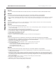
www.zephyronline.com Important Safety Notice READ AND SAVE THESE INSTRUCTIONS WARNING TO REDUCE THE RISK OF FIRE OR ELECTRIC SHOCK, DO NOT USE THIS FAN WITH ANY SOLID-STATE CONTROL DEVICE. WARNING TO REDUCE THE RISK OF FIRE ELECTRIC SHOCK, OR INJURY TO PERSONS, OBSERVE THE FOLLOWING: a. Use this unit only in the manner intended by the manufacturer, if you have questions, contact the manufacturer. b.
TO REDUCE THE RISK OF FIRE, USE ONLY METAL DUCTWORK. CAUTION 7R UHGXFH ULVN RI ¿UH DQG WR SURSHUO\ H[KDXVW DLU RXWVLGH 'R QRW YHQW H[KDXVW DLU LQWR VSDFHV ZLWKLQ ZDOOV FHLOLQJV attics, crawl spaces or garages. Not for use over an outdoor grill. OPERATION $OZD\V OHDYH VDIHW\ JULOOHV DQG ¿OWHUV LQ SODFH :LWKRXW WKHVH FRPSRQHQWV RSHUDWLQJ EORZHUV FRXOG FDWFK RQWR KDLU ¿QJHUV and loose clothing.
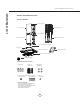
List of Materials www.zephyronline.
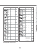
Equivalent number length x used = Duct pieces Total Total 3-1/ 4” x 10” 1 Ft. Rect., straight x( ) = Ft. 6”- 8” Round 30 Ft. wall cap with damper x( ) = Ft. 7” Round, straight 1 Ft. x( ) = Ft. 6”- 8” Round, 30 Ft. roof cap x( ) = Ft. 8” Round, straight 1 Ft. x( ) = Ft. 6” round to 1 Ft. 3-1/ 4” x 10” rect. transition x( ) = Ft. 3-1/ 4” x 10” 15 Ft. Rect. 90 0 elbow x( ) = Ft. x( ) = Ft. 3-1/ 4” x 10” 9 Ft. Rect. 45 0 elbow x( ) = Ft. 6” round to 16 Ft.
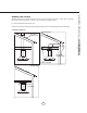
Installation – Mounting Height & Clearance www.zephyronline.com ALWAYS, when possible, reduce the number of transitions and turns. If a long duct run is required, increase duct size from 8” to 10”. If turns or transitions are required: Install as far away from duct opening and as far apart between the two transitions as possible. Minimum mount height between range top to hood bottom should be no less than 26”. A n. mi . B n mi . C x ma D n. mi . E n mi .
NEVER exhaust air or terminate duct work into spaces between walls, crawl spaces, ceiling, attics or garages. All exhaust must be ducted to the outside, unless using the recirculating option. Use single wall rigid metal ductwork only.
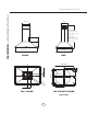
Installation – +RRG 6SHFL¿FDWLRQ www.zephyronline.com 9 13/16” 12 13/16” STANDARD min. ducted - 32” min. recirc. - 36 1/2” max. - 50” 10 5/16” 9 9/16” Z1C-01NA min. ducted - 49” min. recirc. - 53 1/2” max.
Bottom Support Frame (secures to top of blower housing) back Key Holes Ceiling Joists Front Sid 1 Wood Blocking 2 Top Support Frame front - facing controls FIG. C 3 Support Frame Arm FRONT FIG. B Bottom Support Frame B 4 Mounting Screws (pre-installed) Hood Body Cut-Out Shaded Area A XP022220 FIG. A FIG. G 'HWHUPLQH PRXQWLQJ ORFDWLRQ RQ FHLOLQJ DQG WHPSRUDULO\ WDSH SDSHU WHPSODWH LQFOXGHG ZLWK WKH KRRG WR the ceiling.
Installation – Mounting the Hood www.zephyronline.com Cable Lock 2 Top Support Frame Top Duct Covers 1 5 Thick Trim Piece $ FDEOH ORFNLQJ FRQQHFWRU QRW VXSSOLHG PLJKW EH UHTXLUHG by local codes. Check with local requirements and codes, purchase and install appropriate connector if necessary. 4 Bottom Duct Covers Thin Trim Piece 3 Cable Lock FIG. E Bottom Support Frame FIG. D FIG.
We recommend to ALWAYS exhaust air outside of the home by employing existing or installing new duct ZRUN LI SRVVLEOH 7KH KRRG LV PRVW HIIHFWLYH DQG HI¿FLHQW DV DQ H[KDXVW KRRG 2QO\ ZKHQ WKH H[KDXVW RSWLRQ is not possible should you recourse to converting the hood into a recirculating hood.
Features & Controls - Touch Controls www.zephyronline.com Power / Delay Off Display (speed level, delay off, filter clean/change,clean air) clean mesh filter clean air replace charcoal filter Adjust 6 Speed Levels Lights On/Dim/Off 1 Power / Delay Off Button Power Button Function - Button will turn power on and off for entire hood (fan and lights). - Hood will remember the last speed and light level it was turned off at. (Example: Press Button to turn off hood when on fan speed 4 and high lights.
Charcoal Filter Replace Indicator (disabled by default, must be enabled if recirculating hood) - To enable Charcoal Filter Replacement Function: - With hood off, hold Button and Button simultaneously for three seconds. The Graphic will illuminate for three seconds indicating the Charcoal Filter Replacement Function is enabled. - To disable Charcoal Filter Replacement Function: - With hood off, hold Button and Button simultaneously for three seconds.
Maintenance – Hood and Filter Cleaning www.zephyronline.com SURFACE MAINTENANCE: Clean the hood surface periodically with hot soapy water and clean cotton cloth. Do not use corrosive or abrasive detergent or steel wool/scouring pads which will scratch and damage surface. For heavier soil use liquid degreaser. After cleaning it is recommended that you use non-abrasive stainless steel polish/cleaners, to polish and buff out the stainless luster and grain.
Issue Cause What to do After installation, the unit doesn’t work. 1. The power source is not turned ON. 1. Make sure the circuit breaker and the unit’s power is ON. 2. The power line and the cable locking connector is not connecting properly. 2. Check the power connection with the unit is connected properly. 3. The wires on the control board are loose. 3. Make sure the wires on the control board are connected properly. 4. The switch board and control board wirings are disconnected. 4.
Fan Curve Diagrams www.zephyronline.com ALUÀRZ &RQWURO 7HFKQRORJ\ $&7 Some local codes limit the maximum amount of CFM a range hood can move. ACT allows you to control the maximum blower CFM of hoods with Zephyr’s DCBL Suppression System without the need for expensive make up air kits. ACT enables the installer to easily set the maximum blower speed to RQH RI WKUHH PRVW FRPPRQO\ VSHFL¿HG &)0 OHYHOV RU &)0 7KH XVDJH RI $&7 PD\ QRW EH necessary for your installation.
17 Fan Curve Diagrams
Wiring Diagram www.zephyronline.com Model: ZNA-M90BS/E42BS Voltage: 120V 60Hz Power consumption Total: Max. 215W @ 4A Lamp: Max. 3Wx4 Fan: Max. 203W THERMALLY PROTECTED U V W U V W 5A 250V AC-N ON/OFF DOWN UP AC-L LAMP 3RZHU FRQVXPSWLRQ VKRZQ IRU GHIDXOW &)0 EORZHU FRQ¿JXUDWLRQ ACT 590 CFM - Fan Max. 130W @ 1.8A ACT 390 CFM - Fan Max. 70W @ 1A ACT 290 CFM - Fan Max. 35W @ .
PART# Replacement Parts /LJKW %XOE : /(' HDFK $OXPLQXP 0HVK )LOWHU HDFK = % Optional Accessories Recirculating Kit 5HSODFHPHQW &KDUFRDO )LOWHU HDFK Extension Duct Cover ZRC-00NA = ) & Z1C-01NA To order parts, visit us online at http://store.zephyronline.com or call us at 1.888.880.
STAPLE YOUR RECEIPT HERE Proof of the original purchase date is needed to obtain service under warranty Limited Warranty TO OBTAIN SERVICE UNDER WARRANTY OR FOR ANY SERVICE RELATED QUESTIONS, please call: 1-888-880-8368 Zephyr Corporation (referred to herein as “we” or “us”) warrants to the original consumer purchaser (referred to herein as “you” or “your”) of Zephyr products (the “Products”) that such Products will be free from defects in materials or workmanship as follows: Three Year Limited Warranty
Guide d’utilisation, d’entretien et d’installation www.zephyronline.com Napoli ZNA-M90BS ZNA-E42BS Numéro de modèle : _________________ Numéro de série : _________________ APR14.
www.zephyronline.
INSTALLATION Feuille de calcul pour le conduit ........................... Espace libre et hauteur de montage ................... Options d’installation pour le conduit .................. 6SpFL¿FDWLRQV GH OD KRWWH......................................... Montage de la hotte ................................................... Reprise d’air sans conduit ....................................... 5 6 7 8 9-10 11 COMMANDES &RPPDQGHV j HIÀHXUHPHQW .................................. 12 Interface utilisateur ......
Mise en garde de sécurité LISEZ ET CONSERVEZ CES INSTRUCTIONS www.zephyronline.com AVERTISSEMENT POUR RÉDUIRE LES RISQUES D’INCENDIE OU DE DÉCHARGE ÉLECTRIQUE, N’UTILISEZ PAS CET APPAREIL AVEC UN TABLEAU DE COMMANDE À SEMI-CONDUCTEURS. AVERTISSEMENT POUR RÉDUIRE LES RISQUES D’INCENDIE, DE DÉCHARGE ÉLECTRIQUE OU DE BLESSURE, RESPECTEZ CES CONSIGNES : a. N’utilisez cet appareil que de la manière prévue par le fabricant. Si vous avez des questions, communiquez avec le fabricant. b.
POUR RÉDUIRE LES RISQUES D’INCENDIE, N’UTILISEZ QUE DES CONDUITS D’AÉRATION EN MÉTAL. ATTENTION Pour réduire les risques d’incendie et pour évacuer l’air convenablement, assurez-vous de canaliser l’air à l’extérieur de la maison. N’installez pas l’échappement du conduit dans les espaces entre les murs, le plafond, le grenier, les vides sanitaires ou le garage. Cet appareil n’est pas conçu pour être utilisé au-dessus d’un gril extérieur.
Liste du matériel www.zephyronline.
Equivalent number length x used = Duct pieces Total Total 3-1/ 4” x 10” 1 Ft. Rect., straight x( ) = Ft. 6”- 8” Round 30 Ft. wall cap with damper x( ) = Ft. 7” Round, straight 1 Ft. x( ) = Ft. 6”- 8” Round, 30 Ft. roof cap x( ) = Ft. 8” Round, straight 1 Ft. x( ) = Ft. 6” round to 1 Ft. 3-1/ 4” x 10” rect. transition x( ) = Ft. 3-1/ 4” x 10” 15 Ft. Rect. 90 0 elbow x( ) = Ft. x( ) = Ft. 3-1/ 4” x 10” 9 Ft. Rect. 45 0 elbow x( ) = Ft. 6” round to 16 Ft.
Installation – Espace libre et hauteur de montage www.zephyronline.com La hauteur de montage minimale ne devrait pas être moins de 26”. La hauteur de montage maximale ne devrait pas outrepasser 34”. Il est important d’installer la hotte à la hauteur de montage adéquate.
N’évacuez ou ne terminez JAMAIS l’échappement du conduit dans les espaces entre les murs, les vides sanitaires, le plafond, le grenier, ou le garage. Tous les échappements doivent être dirigés à l’extérieur de la maison, à moins que l’option de reprise d’air ne soit utilisée. N’utilisez que des conduits en métal pour cloison simple.
9 13/16” 12 13/16” STANDARD Min. avec conduit - 32” Min. avec reprise d’air - 36 1/2” max. - 50” 9 9/16” Z1C-01NA Min. avec conduit - 49” Min. avec reprise d’air - 53 1/2” max. - 80” 10 5/16” 35 7/16”, 41 15/16” 25 9/16” DEVANT CÔTÉ L/C 1 1/8” 10 1/16” 5 5/16” 2 1/16” Entrée CA 6 3/4” Installation – 6SpFL¿FDWLRQV GH OD KRWWH www.zephyronline.
Cadre de fixation inférieur (est fixé à la partie supérieure du boîtier du ventilateur) Dos Encoches en trou Solives de plafond Front Sid e 1 Bloc de bois 2 Cadre de fixation supérieur Devant – commandes à l’avant FIG. C 3 Bras du cadre de fixation Devant Cadre de fixation inférieur FIG. B B 4 Vis de montage (préinstallées) Boîtier de la hotte Zone de découpage ombragée A XP022220 FIG. A FIG. G 1.
www.zephyronline.com Installation – 0RQWDJH GH OD KRWWH Raccord de câble 2 Cadre de fixation supérieur Pièces de recouvrement supérieures 1 5 Pièce d’habillage large Un raccord de câble (non inclus) pourrait également être exigé par les normes et réglementations locales. Informez-vous des exigences et des normes locales. Achetez et installez le connecteur approprié si nécessaire. 4 Pièces de recouvrement inférieures 3 Pièce d’habillage mince Raccord de câble FIG.
Nous recommandons de TOUJOURS évacuer l’air à l’extérieur de la maison en utilisant le conduit en place ou, s’il y a SRVVLELOLWp HQ LQVWDOODQW XQ QRXYHDX FRQGXLW /D KRWWH HVW SOXV HI¿FDFH ORUVTX¶XWLOLVpH FRPPH V\VWqPH G¶pYDFXDWLRQ G¶DLU 9RXV QH GHYULH] UHFRXULU j OD FRQ¿JXUDWLRQ GH UHSULVH G¶DLU TXH ORUVTX¶LO HVW LPSRVVLEOH G¶LQVWDOOHU XQ FRQGXLW G¶DpUDWLRQ /RUVTXH OD FRQ¿JXUDWLRQ GH UHSULVH G¶DLU HVW FKRLVLH XQ HQVHPEOH GH ¿OWUHV j FKDUERQ GRLW rWUH LQVWDOOp VXU O¶HQVHPEOH GH ¿OWUHV j WDPLV HQ DOXPL
Commandes - &RPPDQGHV j HIÀHXUHPHQW www.zephyronline.com Touche de mise en marche/arrêt automatique Affichage (vitesse, arrêt automatique, nettoyage/changement des filtres, purification d’air) clean mesh filter clean air replace charcoal filter Choix de six vitesses Lumières : Allumer/Veilleuse/Éteindre 1-Touche de mise en marche/arrêt automatique Fonction de mise en marche - La touche permet d’allumer et d’éteindre la hotte (ventilateur et lumières).
Indicateur de remplacement du filtre à charbon (désactivé par défaut, doit être activé avec le mode de reprise d’air) - Pour activer la fonction de remplacement du filtre à charbon : - Lorsque la hotte est éteinte, appuyez et tenez simultanément les touches et pendant trois secondes. Le symbole s’illumine pendant trois secondes, indiquant que la fonction de remplacement des filtres est activée.
Entretien - 1HWWR\DJH GH OD KRWWH HW GHV ¿OWUHV ENTRETIEN DES SURFACES: Nettoyez régulièrement les surfaces de la hotte avec de l’eau savonneuse chaude et un chiffon de coton propre. N’utilisez pas de détergent abrasif ou corrosif, de laines d’acier ou de tampons à récurer; ils égratigneront et endommageront les surfaces. Pour les taches plus tenaces, utilisez du produit dégraissant liquide.
Problème Cause Solution Après l’installation, l’appareil ne fonctionne pas. 1. Le bloc d’alimentation n’est pas allumé 1. Assurez-vous que l’alimentation du disjoncteur et de l’appareil est allumée 2.
Tableau De Rendement Du Ventilateur www.zephyronline.com 'pELW G¶DLU FRQWU{OH GH OD WHFKQRORJLH $&7 Certains codes locaux de limiter le montant maximum de CFM qu’une hotte de cuisinière peut se déplacer. ACT vous permet de contrôler le maximum CFM de les hottes avec le système de répression DCBL à partir de Zephyr sans avoir besoin de coûteux kits pour l’air de remplacement.
Debit (pi3/min) 17 Tableau De Rendement Du Ventilateur Pression (en TQ) Courbe de rendement du ventilateur, 390 CFM Entree en CA: 120V, 60 Hz Diametre du conduit de sortie : 8”
MOTEUR DEL DEL DEL DEL CC Modèle : ZNA-M90BS/E42BS Tension : 120V 60Hz Consommation d’énergie BRANCHEMENT DES COMMANDES W U DEL V W 5A 250V AC-N AC-L BOÎTIER CCI DES COMMANDES PROTÉGÉ THERMIQUEMENT ON/OFF BAS HAUTLAMPE &RQVRPPDWLRQ PRQWUp SRXU GpIDXW GH FRQ¿JXUDWLRQ GX YHQWLODWHXU &)0 ACT 590 CFM - Ventilateur Max. 130W @ 1.8A ACT 390 CFM - Ventilateur Max. 70W @ 1A ACT 290 CFM - Ventilateur Max. 35W @ .55A 18 VERT Max. 215W @ 4A Max. 3Wx4 Lampe : Ventilateur : Max.
Pièces de remplacement Ampoule DEL 3W (chaque) Filtre à tamis en aluminium (chaque) Z0B-0032 50200027 Accessoires optionnels Ensemble de reprise d’air Filtre à charbon de remplacement (chaque) Ensemble de prolongement de recouvrement de conduit ZRC-00NA Z0F-C002 Z1C-01NA Pour commander des pièces, visitez-nous en ligne au www.zephyronline.
AGRAFEZ VOTRE REÇU ICI Garantie limitée Une preuve de la date d’achat originale est nécessaire pour obtenir du service lorsque le produit est sous garantie POUR OBTENIR DU SERVICE SOUS GARANTIE OU POUR TOUTE QUESTION LIÉE À L’ENTRETIEN, veuillez communiquer avec nous au 1-888-880-8368 Zephyr Corporation (désigné aux présentes sous le nom de « nous ») garantit au premier acheteur (désigné aux présentes sous le nom de « vous » ou « votre ») de produits Zephyr (les « Produits ») que lesdits produits sont ex