JAN06.
E page 2 F page 23 S page 45 APPROVED FOR RESIDENTIAL APPLIANCES FOR RESIDENTIAL USE ONLY READ AND SAVE THESE INSTRUCTIONS PLEASE READ ENTIRE INSTRUCTIONS BEFORE PROCEEDING. INSTALLATION MUST COMPLY WITH ALL LOCAL CODES. IMPORTANT: Save these Instructions for the Local Electrical Inspectors use. INSTALLER: Please leave these Instructions with this unit for the owner. OWNER: Please retain these instructions for future reference.
Important safety Notice ..................................................................... 4 Electrical & Installation requirements ............................................. 5 Electrical requirements .............................................................. 5 Before installing the hood ........................................................... 5 List of Materials ................................................................................. 6 Parts supplied: .................................
Important safety Notice READ AND SAVE THESE INSTRUCTIONS CAUTION: FOR GENERAL VENTILATING USE ONLY. DO NOT USE TO EXHAUST HAZARDOUS OR EXPLOSIVE MATERIALS OR VAPORS. WARNING TO REDUCE THE RISK OF FIRE, ELECTRIC SHOCK, OR INJURY TO PERSONS, OBSERVE THE FOLLOWING: A. Use this unit only in the manner intended by the manufacturer. If you have questions, contact the manufacturer. B.
ELECTRICAL REQUIREMENTS Important: Observe all governing codes and ordinances. It is the customers responsibility: To contact a qualified electrical installer. To assure that the electrical installation is adequate and in conformance with National Electrical Code, ANSI/NFPA 70 latest edition*, or CSA Standards C22.1-94, Canadian Electrical Code, Part 1 and C22.2 No.0-M91 - latest edition** and all local codes and ordinances.
List of Materials PARTS SUPPLIED: Blower unit housing Hood canopy Metal filter x 1 Halogen light bulb x 2 Duct covers Remote Control Hardware Packet: Allen spanner x 1 Lower support bracket Template Use, Care and Installation guide 2,9x6,5 screws x 4 (to fix duct cover) 6x20 screws x2 + bushings (to fix vapour screen) 6x70 screws x 2 (to fix duct cover support bracket) 10x60 wall anchors x 2 (to fix duct cover support bracket) 5x45 screws x 3 (2 to fix lower support bracket + 1 to fix blower
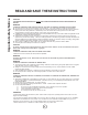
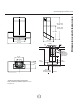
min 35" 13/16* max 49" 7/16* min 35" 13/16 max 43" 2/16 25" 11/16 22" 1/4 19" 11/16 42" - 36" 5/8" ceiling 12" 12" 2"min 7" 1/2* Ducting and conduit area passage(Duct bends are not considered) 14" 6/8 15" 3/4 26" 8" Side Cabinet 5" 3/8 Side Cabinet 13" 35" 7/16 min. cabinets opening widths 24" to 32" bottom of canopy to cooking surface * Ductless (recirculating) version ONLY Note: if necessary order the proper duct cover extension kit. 7 CenterLine Dimensions and clearances www.
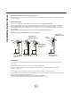
Installation Instructions Closely follow the instructions set out in this manual. All responsibility, for any eventual inconveniences, damages or fires caused by not complying with the instructions in this manual, is declined. VENTING METHODS The hood is equipped with a transition B for discharge of fumes to the outside (Ducting version). Should it not be possible to discharge cooking fumes and vapour to the outside, the hood can be used in the Ductless (recirculating) version.
Duct pieces Equivalent number lenght x used = Duct pieces Total Equivalent number lenght x used = Total 3 1/4 x 10 Rect., straight 1 Ft. x ( )= Ft. 6" Round 30 Ft. wall cap with damper x ( )= Ft. 6 Round,, straight 1 Ft. x ( )= Ft. 6 Round, roof cap 30 Ft. x ( )= Ft. 7", 8 Round,, straight 1 Ft. x ( )= Ft. 6 Round to 3 1/4 x 10 rect. transition 1 Ft. x ( )= Ft. 3 1/4 x 10 Rect.90° elbow 15 Ft. x ( )= Ft. 16 Ft. x ( )= Ft. 3 1/4 x 10 Rect.
Installation Cutout drywall along marked lines. Install each necessary between studs firmly flush with already existing stud front. Make sure all mounting screws will anchor to added studs. Replace drywall and refinish. 1. If possible, disconnect and move freestanding or slide-in range from cabinet opening to provide easier access to rear wall. Otherwise put a thick, protective covering over countertop, cooktop or range to protect from damage or dirt. Select a flat surface for assembling the unit.
15. Install the vapour screen with 2 screws and bushes using the allen spanner included. 16. Hang hood with the 2 mounting hooks. WARNING Excessive Weight Hazard - Use two or more people to move and install range hood. Failure to do so can result in back or other injury. 17.Level the appliance, using a carpenters level across bottom of hood with leveling screws in mounting hooks. 18. Secure hood with 1 screw on bottom.
Installation 19. Connect ducting to transition. Seal with duct tape. Conduit Do not use duct smaller than the transition. For Ductless - recirculating - installations only: provide and install a duct to connect hood transition to deflector (the deflector is available as an extra kit). J-Box cover 20. Electrical connection WARNING Electrical Shock Hazard Warning: Turn off power circuit at the service panel before wiring this unit. 120 VAC, 15 or 20 Amp circuit required.
www.zephyronline.com Installation 24. Install duct cover with 4 screws. Note: Upper Duct Cover may be placed upside down to hide (or unhide) ventless slots. Duct cover support bracket TOP VIEW Duct cover support bracket Upper duct cover Lower duct cover 25. Check all light bulbs to make sure they are secure in their sockets. Turn power on in service panel. Check lights and blower operation. If range hood does not operate: Check that the circuit breaker is not tripped or the house fuse blown.
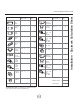
Description of the hood 1 2 3 4 5 6 7 Control panel Grease filter Grease filter release handle Halogen lamp (position and nr.
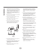
CONTROLS Use the high suction speed in cases of concentrated kitchen vapours. It is recommended that the cooker hood suction is switched on for 5 minutes prior to cooking and to leave in operation during cooking and for another 15 minutes approximately after terminating cooking. Description of control ball and hood operation The control ball is also a light signal: No signal : The hood is switched off. Static green light : Hood is switched on at power level 1 (minimum).
Description of the hood - Remote Control USING THE REMOTE CONTROL This device complies with part 15 of the FCC Rules. Operation is subject to the following two conditions: (1) This device may not cause harmful interference, and (2) this device must accept any interference received, including interference that may cause undesired operation. The remote control may operate in humid environments, but not when placed on wet surfaces.
Prior to any maintenance operation ensure that the cooker hood is disconnected from the power supply. CLEANING The cooker hood should be cleaned regularly internally and externally. For cleaning use a cloth moistened with a neutral liquid detergents. Avoid abrasive detergents. Warning: Failure to carry out the basic standards of the cleaning of the cooker hood and replacement of the filters may cause fire risks. Therefore we recommend oserving these instructions.
Trouble Shooting Issue After installation, the unit doesnt work? Cause What to do 1. The power source is not turned ON. 1. Make sure the circuit breaker and the units power is ON. 2. The power line and the cable locking connector is not connecting properly. 2. Check the power connection with the unit is connected properly. 3. The switch board and control board wirings are disconnected. 3. Make sure the wirings between the switch board and control board are connected properly. 4.
TO OBTAIN SERVICE UNDER WARRANTY: Staple your receipt here. Proof of the original purchase date is needed to obtain service under the warranty. or any Service Related Questions, please call: 1-888-880-8368 TO OBTAIN SERVICE UNDER WARRANTY: You must present proof of original purchase date. Please keep a copy of your dated proof of purchase (sales slip) in order to obtain service under warranty.
List of Parts and Accessories Part Description Part# halogen bulb, 12V 20 W Z0B-0009 metal filter GF02IA remote control (RF) 2009C remote control battery ..394 of 1.5V.
www.zephyronline.