Models: DLI-E30ASX, DLI-E36ASX Downdraft Hood For use with these blowers (purchase blowers separately): Model DBI-600A - Internal Models CBE-1000 - External Models PBN-1000A - In-Line Français p. 35 APR19.0101 READ AND SAVE THESE INSTRUCTIONS Register your product online at: www.zephyronline.com Español p.
Table of Contents Safety Information................................................................................................................................................................................... 3 Contents................................................................................................................................................................................................... 4 Specifications..........................................................................
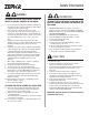
Safety Information WARNING WARNING TO REDUCE THE RISK OF FIRE, ELECTRIC SHOCK, OR INJURY TO PERSONS, OBSERVE THE FOLLOWING: TO REDUCE THE RISK OF INJURY TO PERSONS IN THE EVENT OF A RANGE TOP GREASE FIRE, OBSERVE THE FOLLOWING: 1. Use this unit only in the manner intended by the manufacturer. If you have questions, contact the manufacturer at the address or telephone number on the back page. 2.
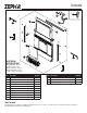
Contents C x8 C1 BB D B A N G x2 M x4 E H IL J ELECTRICAL SPECIFICATIONS Model DBI-600A - Internal 120 VAC • 60 Hz • 3.0 A Models CBE-1000 - Exterior Models PBN-1000A - In-Line 120 VAC • 60 Hz • 6.0 A (max.) Part Description Quantity Part Description M Flip door 1 Quantity A Upper support bracket (left) 1 B Downdraft ventilator housing 1 N LED light strip 1 C End cap trim (left) 1 BB #10 x .
Planning Before You Begin Taking Measurements Due to its flexible design, this downdraft system can be used to exhaust airborne contaminants when cooking with a variety of gas or electric cooking appliances - including cooktops, rangetops, slide-in ranges and free-standing ranges. • Refer to the cooktop installation instructions for dimensions of cooktop, countertop cut-out, and cabinet requirements. However, it is recommended that oversized cabinets be used for easier installation.
Planning Ducting Configurations (continued) Front Exhaust with DBI-600A Blower (through cabinet) Downdraft DBI-600A Blower 8" Straight Duct Electrical Panel 8" Round Elbow Front Exhaust with DBI-600A Blower (through cabinet) and Recirculating Kit Front Exhaust with DBI-600A Blower and Recirculating Kit Downdraft DBI-600A Blower Downdraft DBI-600A Blower 8" Straight Duct Electrical Panel Electrical Panel 8" Round Elbow 8" Straight Duct ZRC-00LF (Recirculating Kit) ZRC-00LF (Recirculating Kit) 6
Planning Ducting Configurations (continued) Side Exhaust with DBI-600A Blower and Recirculating Kit Side Exhaust with DBI-600A Blower Downdraft Downdraft 1-7/8" to 8" Round Transition 1-7/8" to 8" Round Transition DBI-600A Blower 8" Straight Duct DBI-600A Blower 8" Straight Duct 8" Straight Duct 8" Round Elbow ZRC-00LF Recirculating Kit Refer to ZRC-00LF manaul for further recirculating kit installation instructions .
Planning Ducting Configurations (continued) Front Exhaust with Remote Blower Downdraft 10" Straight Duct * * To one of the following: Model CBE-1000 External Blower • Model PBN-1000A In-line Blower 10" Round Elbow Note: External or in-line blowers require 10" ducting.
Planning Ducting Configurations (continued) Rear Exhaust with Remote Blower Downdraft 10" Round Elbow 1-7/8" to 10" Round Transition 10"Straight Duct * * To one of the following: Model CBE-1000 External Blower • Model PBN-1000A In-line Blower Note: External or in-line blowers require 10" ducting.
Planning Cabinet Cutouts Below, Side or Rear Ducting Cutouts CAUTION BEFORE CUTTING HOLE IN CABINET FOR DUCTWORK, check for interference with floor joists, wall studs, electrical wiring, or plumbing. /8" 5-7 cm) 9 . (14 Use the dimensions in illustrations to help plan how and where to provide duct access through your cabinet. Generally, 1-7/8" x 19" rectangular duct will be used through left, right, below and back of cabinet - while 8" round duct will be used through cabinet floor using DBI-600A blower.
Planning Cabinet Cutouts (continued) 10" External or In-line Blower Ducting Cutout DBI-600A Blower Ducting Cutout Appliance Cutout Appliance Cutout Ce nte Ce r li ne nte of do wn ne dra ft Ø10" (25.4 cm) 2" ) 1/ m 1- 8 c . (3 Ø8" (20.3 cm) 8" ) 5/ cm 5- .3 4 (1 8" ) 5/ cm 8- .3 4 (1 Dimensions based off of - 10" round elbow DBI-600A Blower Ducting - Remote Location Cutout Appliance Cutout Ce r li nte r li ne of do wn dra ft Ø8" (20.3 cm) 8" ) 5/ cm 7- .
Preparing the Downdraft Side or Rear Ducting Front Ducting 1 1 B B H G Remove a discharge cover (G) from sides or rear of downdraft (B). Note: Only remove one cover. Remove front panel cover (H) from downdraft (B). 2a 2a B 1 2 B Install a transition and rectangular ductwork to downdraft (B). (Rectangular ductwork sold separately) Install 8" or 10" remote discharge plate to downdraft (B).
Preparing the Downdraft Electrical Panel in Remote Location Final Assembly 3 1 B B E I E Remove electrical panel (I) from downdraft (B). Electrical panel connector cable legth is 2 feet. Optional 5 foot cable extension available. Note: Option for most installations. Required for DBI-600A blower installations when discharge is down. Attach previously removed lower support legs (E) to downdraft (B) using one nut for each leg. 4 2 A Install electrical panel in remote location.
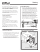
Installation Cutting Counter Top Opening 6a Cooktop 6d Gass Cooktop seal kit is recommended if installing a gas cooktop . See Optional Accessory page for more information. 6b Range trim kit may be required. See Optional Accessory page for more information. Cooktop with Oven 7 Gas Cooktop seal kit is recommended if installing a gas cooktop. See Optional Accessory page for more information. 6c Range Place appliance. Note: Cook top shown.
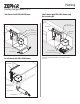
Installation Cutting Counter Top Opening (continued) Install Housing into Cabinet (continued) 12 9 1 E 1 AA 2 Remove cook top/appliance and cut opening. Attach support legs (E) to bottom of cabinet with two screws (AA) per leg. Tighten hex screws. Note: If cabinet bottom is removed, use blocks as spacers between floor and support legs. Install Housing into Cabinet 13 10 1 A 2 Set housing into cabinet.
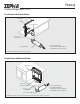
Installation Installing Finish Trim 15 Installing Finish Trim (continued) 17 2 D TOP VIEW C Washer B 2 2 1/16" Gap Trim Retaining Washer C 1 3 1 C Flush Place retaining washer on left trim cap (C). Insert hinge pin into slot of the flip door. Position left trim cap and flip door. Align trim caps and complete assembly by tightening trim cap nut. Note: Make sure trim sits flat on countertop surface, is flush with top door, and has 1/16” GAP between trim and top door.
Electrical Wiring Installation 600 CFM WIRING SET UP DBI-600A Blower only White (common) Blue (low) Lift Grey (med.) Downdraft Black (high) CAUTION Orange (high) Green (ground) All electrical wiring should be done by a qualified person(s) in accordance with all applicable codes and standards. • • Blue (low) Red (med.
Electrical Wiring Installation Exterior or In-Line Blower only White (Common) CAUTION Blue (Low) Lift Gray (Med.) Downdraft Black (High) All electrical wiring should be done by a qualified person(s) in accordance with all applicable codes and standards. Orange (High) Greed (Ground) • If using a remote blower (purchase separately), the system draws 6.0 Amps (max.) and requires a 120 VAC, 60 Hz circuit. • The unit has a 30 in. long power cord with a 3-pronged plug attached to the electrical panel.
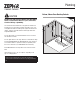
Appliance Installation/Operation Install Cooking Appliance Note: Accurate alignment of cooking appliance and downdraft is necessary to ensure that there is no interference when air vent is raised and lowered. There should be a gap of 1/32 " - 1/16 " between the back of the cooktop and the front of the downdraft cover. 1. Align the cooking appliance with downdraft and fasten appliance in place following appliance instructions.
Use and Care Cooking CAUTION WARNING Always disconnect electric power supply before cleaning and/or servicing unit. To clean inside chimney: Lift FRONT PANEL up and out and take out the GREASE FILTERS. Use a mild detergent. DO NOT USE ABRASIVE CLOTH, STEEL WOOL PADS, OR SCOURING POWDERS. Replace filters and front panel before using downdraft. Always turn the downdraft blower on before you begin cooking to establish an air flow in the kitchen.
Optional Accessories Optional Accessories Accessory Description Accessory Description Model DDA-0002 REMOTE UP/DOWN CONTROL MODEL 11030132 EXTENSION CABLE - 5-FT. Use where electrical panel is remotely mounted. Extends electrical panel cable an additional 5 feet. Use when you cannot reach the UP/ DOWN Button on the downdraft chimney. Can be located on counter top, face of cabinetry or on the side cabinet of an island.
Optional Accessories Optional Accessories (continued) Accessory Description MODEL DDE-0001 END CAP TRIM EXTENSION +1" WIDTH - LH & RH Use left and right to increase the overall trim width by 1". MODEL 54190053 FRONT PANEL ROUGH-IN PLATE 8" ROUND Use where 8" round duct or elbow attaches to front of airbox (Model DBI600A used as remote blower installation).
Blower duct routing configuration A Internal Blower (DBI-600A) - Front Mounted to Downdraft MODEL DBI-600 Internal Blower (sold separately) (“Down” discharge shown. Blower can also be rotated for “Left” or “Right” discharge.) 8-inch Round Straight Duct* 8-inch Round Wall Cap* Electrical Panel (Mount in remote location) 8-inch Round Elbow* MODEL 11030132 5-foot Extension Cable (sold separately) (Only required if electrical panel is more than 2-feet away from downdraft.
Blower duct routing configuration B Internal Blower (DBI-600A) - Remote Mounted - Front Outlet MODEL 54190053 8-inch Round Front Rough-in Plate (sold separately) 8-inch Round Elbow* Electrical Panel (Can be mounted in remote location) 8-inch Round Straight Duct* MODEL 11030132 5-foot Extension Cable (sold separately) (Only required if electrical panel is mounted in a remote location more than 2-feet away from downdraft. Use up to 2 extension cables connected together.
Blower duct routing configuration C Internal Blower (DBI-600A) - Remote Mounted - Side Outlet MODEL AK00072 1-7/8-inch x 19-inch Rectangular Transition (sold separately) (Only required to extend duct along back of cabinet.) MODEL AK00080 1-7/8-inch x 19-inch Rectangular Duct (sold separately) (Only required to extend duct along back of cabinet.
Blower duct routing configuration D Internal Blower (DBI-600A) - Remote Mounted - Rear Outlet MODEL AK00080 1-7/8-inch x 19-inch Rectangular Duct (sold separately) MODEL AK00070 1-7/8-inch to 8-inch Round Transition (sold separately) MODEL AK00072 1-7/8-inch x 19-inch Rectangular Transition (sold separately) MODEL DBI-600A Internal Blower (sold separately) (Mounted in adjacent cabinet) 8-inch Round Elbow* 8-inch Round Straight Duct* 8-inch Round Straight Duct* 8-inch Round Straight Duct* 8-inch Round
Blower duct routing configuration E Internal Blower (DBI-600A) - Remote Mounted - Below Outlet MODEL 11030132 5-foot Extension Cable (sold separately) (Only required if electrical panel is mounted in a remote location - more than 2-feet away from downdraft. Use up to 2 extension cables connected together.) Electrical Panel (Can be mounted in remote location.
Blower duct routing configuration F External or In-Line Blower - Front Outlet MODEL 54190054 10-inch Round Front Rough-in Plate (sold separately) MODEL 11030132 5-foot Extension Cable (sold separately) (Only required if Electrical Panel is mounted in a remote location - more than 2-feet away from downdraft. Use up to 2 Extension Cables connected together.) 10-inch Round Elbow* Electrical Panel (Can be mounted in remote location.) (Standard 120 VAC wiring rated for 6A minimum - sold separately.
Blower duct routing configuration G External or In-Line Blower - Side or Rear Outlet MODEL AK00072 1-7/8-inch x 19-inch Rectangular Transition (sold separately) (Only required to extend duct along back of cabinet) MODEL AK00080 1-7/8-inch x 19-inch Rectangular Duct (sold separately) (Only required to extend duct along back of cabinet.) MODEL 11030132 5-foot Extension Cable (sold separately) (Only required if Electrical Panel is mounted in a remote location - more than 2-feet away from downdraft.
Blower duct routing configuration H External or In-Line Blower - Below Outlet MODEL 11030132 5-foot Extension Cable (sold separately) (Only required if electrical panel is mounted in a remote location - more than 2-feet away from downdraft. Use up to 2 extension cables connected together.) Electrical Panel (Can be mounted in remote location.) MODEL AK00071 1-7/8-inch x 19-inch to 10-inch Round Transition (sold separately) (Standard 120 VAC wiring rated for 6 A minimum - sold separately.
Wiring Diagram NOT USED 31
Dimensional Drawing 30 ”, 18” 36 25 ” -1/ 2”, 31 -1/ 2” 2” 2” / -1 2 15-1/8” 6-1/4” 29-3/8” 27 -1/ 4”, 16 -1/ 4” 33 -1/ 4” 5” 1/2” 2- 32
Warranty Zephyr Ventilation, LLC (referred to herein as “we” or “us”) warrants to the original consumer purchaser (referred to herein as “you” or “your”) of Zephyr products (the “Products”) that such Products will be free from defects in materials or workmanship as follows: Two Year Limited Warranty for Parts: For two years from the date of your original purchase of the Products, we will provide, free of charge, Products or parts (including LED light bulbs, if applicable) to replace those that failed due t