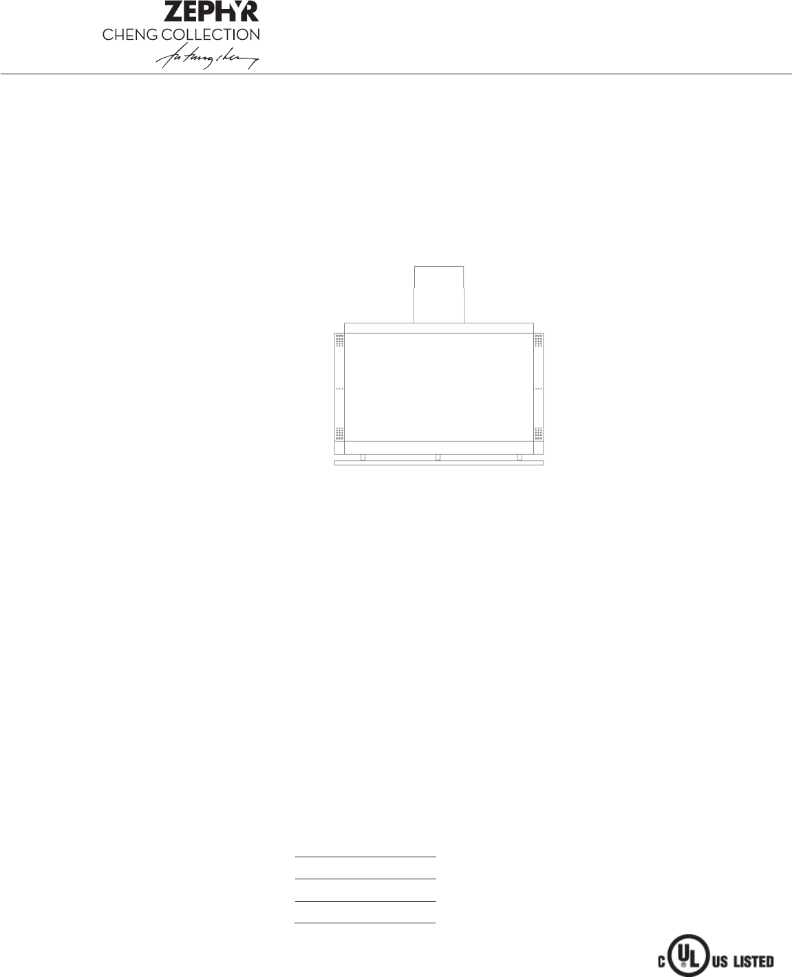
Use, Care, and Installation Guide www.zephyronline.com Shade CSH -E36SX CSH -E42SX CSH -E48SX Model number: Serial number: Date of Purchase: Sales Dealer: MAY07.0101 © Zephyr Corporation.
www.zephyronline.
2 3 INSTALLATION Ducting Calculation Sheet ............................... Mounting Height and Clearance ..................... Ducting .................................................................. Specifications ....................................................... Internal Blower .................................................... Preparing Hood for External Blower .............. Mounting the Hood ............................................
www.zephyronline.com Important safety Notice READ AND SAVE THESE INSTRUCTIONS WARNING TO REDUCE TH E R IS K O F FIR E O R E LE C TR IC SHOC K, DO NOT USE TH IS FAN W ITH ANY S O LID-S TATE SPE E D CONTROL DEV IC E. WARNING TO RE DUCE TH E R IS K O F FIR E, E LE C TR IC SH O C K, O R INJU RY TO P E R SON S, O B S E RVE TH E FO LLO W ING: a. Use this unit only in the manner intended by the manufacturer, If you have questions, contact the manufacturer. b.
Lis t of M a teria ls MODEL: CSH-ExxSX 1 - Hood Body 2 - Baffle Filters (1 - 36” model) 4 - GU-10, 120V, 50W Halogen Bulbs 1 - Hood Door 2 - Telescopic Duct Covers 1 - Ceiling Mounting Bracket 1 - HARDWARE PACKET 7 - 2” wood screws 7 - anchors 7 - 1/2” washers 4 - screws (Dimension 5 x 15mm) 4 - adhesive fastener (to hold cable tie) 4 - cable tie 1 - HARDWARE PACKET, EXTERNAL BLOWER KIT 1 - 8” collar 1 - external blower connection box 10 - 1/2” self tapping screws 6 - 4mm internal diameter washer 1 - wirin
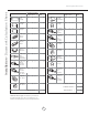
Ins ta lla tion - Ductwork C a lcula tion S heet www.zephyronline.com Equivalent number length x used = Duct pieces Equivalent number length x used = Duct pieces Total Total 3 1/4” x 10” Rect., straight 1 Ft. x( ) = Ft. 6” Round 30 Ft. wall cap with damper x( ) = Ft. 7” Round, straight 1 Ft. x( ) = Ft. 6” Round, roof cap 30 Ft. x( ) = Ft. 7” Round, straight 1 Ft. x( ) = Ft. 6” round to 3 1/4” x 10” rect. transition 1 Ft. x( ) = Ft. 3 1/4” x 10” Rect. 90 0 elbow 15 Ft.
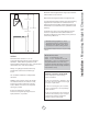
Maximum mount height should be no higher than 32". Min 36"- Max 40" It is important toinstall the hood at the proper mounting height. Hoods mountedtoo low could result in heat damage and fire hazard; while hoods mountedtoo high will be hard to reach and will loose its performance and efficiency. Min 96"- Max 108 Min 24"-Max 32" If available, also refer to range manufacturer's height clearance requirements and recommended hood mounting height above range. Always check your local codes for any differences.
Installation - Ducting www.zephyronline.com WARNING FIRE HAZARD NEVER exhaust air or terminate duct work into spaces between walls, crawl spaces, ceiling, attics, or garages. All exhaust must be ducted to the outside. Use single wall rigid Metal ductwork only. Fasten all connections with sheet metal screws and tape all joints w/ certified Silver Tape or DuctTape.
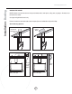
12” 10” Min. 36” Max 40” 8“-12" 20" 31 1/4” 8" 10” or 24” Installation - Specifications 16 7/8” 30", 36”, 42” DOOR INSERT PANEL 1/8” (3.
Ins ta lla tion - Interna l B lower www.zephyronline.com ATTENTION The following are intructions for installing internal blower model CBI-600. For instructions on preparing for external blower model CBE-1000 please turn to page “10”. Before installing, verify that motor spins freely. The internal blower kit consists of the blower and capacitor box with wiring. 1. Position blower as shown. 2. Att ach blower to flange as shown using the provided 1/2” 5x15mm screws with washers. 3.
6. Re-attach grounding screw to finish installation of capacitor box. Refer to Fig-A on previous page. 7. Attach short capacitor connector to blower connector. 8. Att ach long capacitor connector to control board connector. 9. Use plastic tie to hold wiring together. 10. Remove wood block Final view of internal blower install. Continue to page “12” for hood installation instructions. 9 Installation - Internal Blower 5. Remove existing grounding screw and attach grounding wire from capacitor box.
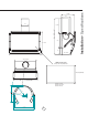
Ins ta lla tion - P repa ring E xterna l B lower www.zephyronline.com ATTENTION The following are intructions on preparing your hood for installation with external blower model CBE-1000. For instructions on installing internal blower model CBI-600 please turn to page “8”. NOTE: Please refer to the CBE-1000 manual for external blower mounting instructions. The external blower kit consists of an 8” collar, and external blower wiring box. The external blower is purchased separately. 1.
7. Secure cover to box with provided screw. 8. Attach connector from external blower wiring box to control board box connector inside hood. 9. Attach grounding wire from external blower wiring box to grounding screw of the junction box. Refer on Fig-A in diagram below . 10. Final view of external blower preparation Continue to page “12” for hood installation instructions. For external blower installation please refer to the manual included with the external blower.
Installation - Preparing Hood www.zephyronline.com Duct Cover Ceiling Bracket Duct Cover Ceiling Bracket B 20” 24” C 16 1/4” A min 24” max 32” C/L C/L Attach screws to ceiling bracket 1. Measure from cooking surface to hood bottom, level and mark line A. 2. Plum and mark center line. 3. Mark mounting height line B (20” from line A). This is the top of the hood. 4. Measure up, 16 1/4” from line A and mark mounting spread from C/L. Line C (24”). 5.
)NSTALLATION -OUNTING (OOD 4OP GAP BETWEEN BRACKET AND WALL " # ! "OTTOM !TTACH SCREWS TO BOTH SIDES OF THE DUCT COVERS AND SECURE TO CEILING BRACKET v %LECTRICAL 0LACE WALL BRACKET ON LINE # 0OSITION TOP OF WALL BRACKET SO IT IS EVEN WITH THE v MOUNTING SPREAD -AKE SURE BRACKET IS ATTACHED TO WALL AS SHOWN IN THE DIAGRAM 4HE TOP OF THE WALL BRACKET SHOULD HAVE A GAP BETWEEN IT AND THE WALL 4HE BOTTOM SHOULD BE FLUSH AGAINST THE WALL 5SE v WOOD SCREWS TO ATTACH BRACKET TO WALL 5SE AN
Fea tures & C ontrols - Touch C ontrols & F ea tures www.zephyronline.com 1. Blower On/Off By pressing , the blower is switched On and Off. 2. Speed Selection The 3 speed levels are selected by presing level selected. to decrease and to increase speed level. T he display indicates 3. Delay Off This is used for programmed shut down of blower and lights 15 minutes after the function is activated. Press once, a dot flashes in the lower right hand side of display indicating the function is on.
Filter Clean Reminder: When flashes on display, the baffle filters installed are required to be cleaned. This will occur after every 30 hours of use. Clean Filters display flashes Re-setting Function: Reset the Filter Clean Reminder timer when filters are cleaned and re-installed (with hood off). Press and hold for approx. 5 seconds, the display will appear; hold for approximately 5 seconds until on display disappears .
Features & Controls - Remote Features www.zephyronline.com Infrared Receiver / Transmitter: By aiming the infrared transmitter (located at the top of the remote control) to the infrared receiver (located on the bottom of the range hood) you can control the following features remotely: 1 2 1 LightsOn/Off,Dim 2 Adjust3 SpeedLevels 3 BlowerOn/Off Lights On/Off/ Dim Switch lights On and Off by pressing key Speed Selection The 3 speed levels are selected by pressing .
The original stainless steel insert panel may be replaced with any 1/8” fired rated piece of material. The panel dimensions for each model are as follows; Width Height Thickness CSH-E48SX 42 7/8” 24 5/8” 1/8” CSH-E42SX 36 13/16” 24 5/8” 1/8” CSH-E36SX 31 5/16” 24 5/8” 1/8” Door Insert Panel Insert Panel Dimensions: 1. 2. 3. 4. Using a Phillips head screwdriver, remove (3) screws [ a ] from the top cap. Remove top cap [ b] and slide front insert panel [ c] up to remove from door.
Clean periodicallywith hot soapy water and clean cotton cloth. Do not use corrosive or abrasive detergent , or steel wool/scouring pads which will scratch and damage surface. For heavier soil use liquiddegreaser. After cleaning, you may use non-abrasive stainless steel polish/ cleaners, to polish and buff out the stainless luster and grain. Always scrub lightly, with clean cotton cloth, and with the grain. Do not use any product containing chlorine bleach. Do not use “orange” cleaners.
M a intena nce - Lights www.zephyronline.com Replacing Light Bulbs: CA UTION: Light bulbs become extremely hot when turned on. DO NOT touch bulbs until switched off and cooled. Touching hot bulbs may cause serious burns. Make sure all power is turned off and bulbs are not hot. Remove bulb by pressing both ends of the metal retaining clip together, the light socket will now protude from the hood allowing you to remove the bulb.
Trouble S hooting www.zephyronline.com Issue Cause What to do After installation, the unit doesn’t work? 1. The power source is not turned ON. 1. Make sure the circuit breaker and the unit’s power is ON. 2. The power line and the cable locking connector is not connecting properly. 2. Check the power connection with the unit is connected properly. 3. The switch board and control board wirings are disconnected. 3.
Halogen Bulb G U-10, 120V, 50W Part# Z0B-0020 Accessory Descr iption Part# Internal Blower, 600 cfm CBI-600 External Blower, 1000 cfm CBE-1000 Duct Cover Extension Kit Z1C-00SH 21 List of Parts and Accessories Part Descr iption