Use, Care, and Installation Guide www.zephyronline.com CACHE CCA-E30ASX CCA-E36ASX CCA-E48ASX Model number: Serial Number: Date of Purchase: Sales Dealer: NOV12.
www.zephyronline.
INSTALLATION Ducting Calculation Sheet ....................................... Mounting Height & Clearance................................ Ducting Options ........................................................... Hood Specifications ................................................... Preparing the Electrical Wires ............................... Internal Blower (Vertical Ducting)......................... Internal Blower (Horizontal Ducting) ................... External Blower Prepartion ..................
www.zephyronline.com Important Safety Notice READ AND SAVE THESE INSTRUCTIONS WARNING TO REDUCE THE RISK OF FIRE OR ELECTRIC SHOCK, DO NOT USE THIS FAN WITH ANY SOLID-STATE CONTROL DEVICE. WARNING TO REDUCE THE RISK OF FIRE ELECTRIC SHOCK, OR INJURY TO PERSONS, OBSERVE THE FOLLOWING: a. Use this unit only in the manner intended by the manufacturer, if you have questions, contact the manufacturer. b.
To reduce the risk of fire and electric shock, install this range hood only with external blower models CBE-1000, rated maximum 6.2 amps, 120V AC 60Hz or internal blowers manufactured by Zephyr Ventilation, models CBI-600A. WARNING TO REDUCE THE RISK OF FIRE, USE ONLY METAL DUCTWORK. CAUTION To reduce risk of fire and to properly exhaust air outside - Do not vent exhaust air into spaces within walls, ceilings, attics, crawl spaces or garages.
List of Materials www.zephyronline.
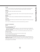
Equivalent number length x used = Duct pieces Total Total 3-1/ 4” x 10” 1 Ft. Rect., straight x( ) = Ft. 6”- 8” Round 30 Ft. wall cap with damper x( ) = Ft. 7” Round, straight 1 Ft. x( ) = Ft. 6”- 8” Round, 30 Ft. roof cap x( ) = Ft. 8” Round, straight 1 Ft. x( ) = Ft. 6” round to 1 Ft. 3-1/ 4” x 10” rect. transition x( ) = Ft. 3-1/ 4” x 10” 15 Ft. Rect. 90 0 elbow x( ) = Ft. x( ) = Ft. 3-1/ 4” x 10” 9 Ft. Rect. 45 0 elbow x( ) = Ft. 6” round to 16 Ft.
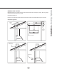
Installation – Mounting Height & Clearance www.zephyronline.com Minimum mount height between range top and hood bottom should be no less than 24”. Maximum mount height should be no higher than 32”. It is important to install the hood at the proper mounting height. Hoods mounted too low could result in heat damage and fire hazard; while hoods mounted too high will be hard to reach and will lose its performance and efficiency. in. ” m x.
NEVER exhaust air or terminate duct work into spaces between walls, crawl spaces, ceiling, attics or garages. All exhaust must be ducted to the outside. Use metal ductwork only. Fasten all connections with sheet metal screws and tape all joints with certified Silver Tape or Duct Tape.
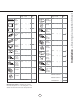
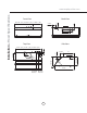
Back View Front View 2-3/4” 4-3/16” 1-1/8” 2” 1-1/4” 29-61/64” - (30“), 35-61/64” - (36“), 47-29/32” - (48”) 9-29/32” Side View Top View 27-7/8” - (30“), 33-7/8” - (36“), 45-53/64 - (48”) 2-3/4” 3-19/32” 2” 12” 2” 5-5/32” 4-3/16” 5-5/32” R2 0” 22-1/8” ext. blower knock-out AC power knock-out 8 10-23/64” 57- 7/8” 7/ 8” or 11-31/32” 8-5/8” Installation – Hood Specifications www.zephyronline.
WARNING All Electrical work must by performed by qualified electrician or person with similar technical know how and background. For personal safety, remove house fuse or open circuit breaker before beginning installation. Do not use extension cord or adapter plug with this appliance. Follow national electrical codes or prevailing local codes and ordinances.
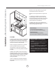
Installation – Internal Blower (Vertical Ducting) www.zephyronline.com INTERNAL BLOWER PREPARATION – VERTICAL DUCTING 1. Attach capacitor box to inside of hood using two M4*10 screws included with internal blower. 2. Attach green ground wire to ground screw on hood. 3. Connect 6 pin male connector from capacitor box to 6 pin female connector on control board box. 4. Place 6” round mounting plate on top of hood and secure using eight M4*8 screws. 5. Install internal blower into hood. 6.
Installation – Internal Blower (Vertical Ducting) 7. Connect 9 pin male connector from blower to 9 pin female connector on capacitor box.
Installation – Internal Blower (Horizontal Ducting) www.zephyronline.com INTERNAL BLOWER PREPARATION – HORIZONTAL DUCTING 1. Attach capacitor box to inside of hood using two M4*10 screws included with internal blower. 2. Attach green ground wire to ground screw on hood. 3. Connect 6 pin male connector from capacitor box to 6 pin female connector on control board box. 4. Place solid mounting plate on top of hood and secure using eight M4*8 screws. 5. Remove rectangular cap from back of hood.
8. Install blower with round to rectangular adapter into hood. 9. Mount blower brackets to hood using two 3/16” * 3/8” screws for each bracket. Screws are included with internal blower. 10. Install rectangular starting collar to back of hood using six M4*8 screws recently removed from rectangular cap (three screws on each side). Install four additional M4*8 screws in the top and bottom middle of rectangular starting collar. Check and verify inner adapter is firmly secured. 11.
Installation – External Blower Preparation www.zephyronline.com EXTERNAL BLOWER PREPARATION 1. Place 8” round mounting plate on top of hood and secure using eight M4*8 screws. 2. Install threaded cable lock and external blower wiring through the knockout next to the electrical wiring knockout. 3. Place cap over threaded cable lock and secure by turning cap clockwise. NOTE: Due to the size of the cap, it may be easier to install it after the hood has been mounted. 4.
1. Select preferred duct location (internal blower vertical or horizontal, external blower - vertical only). 5. Duct opening cutout 2. Begin installation by removing the baffle filters. 3. Reinforce cabinet with 1” x 2” wood strips if additional strengthening is required. Must be placed inside frameless cabinets. duct/silver tape 4. Temporarily position the range hood in the desired mounting location. Measure and mark the mounting holes, duct and electrical locations with a pencil.
Features & Controls – Touch Controls www.zephyronline.com 4 Lights On/Off/Dim 3 5 Min Delay Off 5 Display (Speed level, Delay Off Indicator) 1 Blower On/Off 2 Adjust 3 Speed Levels 1 Blower On/Off By pressing , the blower is switched On and Off. When switched on, the blower starts up on the same speed it was turned off at. When switched off the entire hood powers off, including the lights. 2 Speed Selection The 3 speed levels are selected by pressing to decrease and to increase speed level.
Baffle Filter Clean Indicator When F flashes on display, the baffle filters installed are required to be cleaned. This will occur after every 30 hours of use. Clean Filters display < F > flashes F Re-setting Function Reset the filter clean reminder timer when filters are cleaned and re-installed (with hood off). Press and hold for approximately 5 seconds, the display will appear; hold for approximately 5 seconds until F on display disappears .
Maintenance – Cleaning and Installing Filters www.zephyronline.com SURFACE MAINTENANCE: Clean periodically with hot soapy water and clean cotton cloth. Do not use corrosive or abrasive detergent, or steel wool/scoring pads which will scratch and damage surface. For heavier soil use liquid degreaser. After cleaning, you may use non-abrasive stainless steel polish/ cleaners, to polish and buff out the stainless luster and grain.
CAUTION: Light bulb becomes extremely hot when turned on. DO NOT touch bulb until switched off and cooled. Touching hot bulbs could cause serious burns. Make sure all power is turned off and bulbs are not hot. Remove by turning bulb counter clockwise. Note: Bulb does not unscrew; it turns 60 degrees, stops and falls out. If bulbs are difficult to turn due to prolonged use, firmly attach the provided glass suction cup and turn.
Troubleshooting www.zephyronline.com TROUBLESHOOTING PROCEDURES FOR CACHE Issue Cause What to do After installation, the unit doesn’t work. 1. The power source is not turned ON. 1. Make sure the circuit breaker and the unit’s power is ON. 2. The power line and the cable locking connector is not connecting properly. 2. Check the power connection with the unit is connected properly. 3. The switch board and control board wirings are disconnected. 3.
STAPLE YOUR RECEIPT HERE Proof of the original purchase date is needed to obtain service under warranty Limited Warranty TO OBTAIN SERVICE UNDER WARRANTY OR FOR ANY SERVICE RELATED QUESTIONS, please call: 1-888-880-8368 Zephyr Corporation (referred to herein as “we” or “us”) warrants to the original consumer purchaser (referred to herein as “you” or “your”) of Zephyr products (the “Products”) that such Products will be free from defects in materials or workmanship as follows: Three Year Limited Warranty