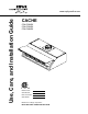
Use, Care, and Installation Guide www.zephyronline.com CACHE CCA-E30ASX CCA-E36ASX CCA-E48ASX Model number: Serial Number: Date of Purchase: Sales Dealer: DEC06.
www.zephyronline.
INSTALLATION Ducting Calculation Sheet ....................................... Mounting Height & Clearance................................ Ducting Options ........................................................... +RRG 6SHFL¿FDWLRQV ................................................... Preparing the Electrical Wires ............................... Internal Blower (Vertical Ducting)......................... Internal Blower (Horizontal Ducting) ................... External Blower Prepartion ...................
www.zephyronline.com Important Safety Notice READ AND SAVE THESE INSTRUCTIONS WARNING TO REDUCE THE RISK OF FIRE OR ELECTRIC SHOCK, DO NOT USE THIS FAN WITH ANY SOLID-STATE CONTROL DEVICE. WARNING TO REDUCE THE RISK OF FIRE ELECTRIC SHOCK, OR INJURY TO PERSONS, OBSERVE THE FOLLOWING: a. Use this unit only in the manner intended by the manufacturer, if you have questions, contact the manufacturer. b.
7R UHGXFH WKH ULVN RI ¿UH DQG HOHFWULF VKRFN LQVWDOO WKLV UDQJH KRRG RQO\ ZLWK H[WHUQDO EORZHU PRGHOV &%( UDWHG maximum 6.2 amps, 120V AC 60Hz or internal blowers manufactured by Zephyr Ventilation, models CBI-600A. WARNING TO REDUCE THE RISK OF FIRE, USE ONLY METAL DUCTWORK. CAUTION 7R UHGXFH ULVN RI ¿UH DQG WR SURSHUO\ H[KDXVW DLU RXWVLGH 'R QRW YHQW H[KDXVW DLU LQWR VSDFHV ZLWKLQ ZDOOV FHLOLQJV DWWLFV crawl spaces or garages.
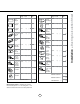
List of Materials www.zephyronline.
Equivalent number length x used = Duct pieces Total Total 3-1/ 4” x 10” 1 Ft. Rect., straight x( ) = Ft. 6”- 8” Round 30 Ft. wall cap with damper x( ) = Ft. 7” Round, straight 1 Ft. x( ) = Ft. 6”- 8” Round, 30 Ft. roof cap x( ) = Ft. 8” Round, straight 1 Ft. x( ) = Ft. 6” round to 1 Ft. 3-1/ 4” x 10” rect. transition x( ) = Ft. 3-1/ 4” x 10” 15 Ft. Rect.90 0 elbow x( ) = Ft. x( ) = Ft. 3-1/ 4” x 10” 9 Ft. Rect.45 0 elbow x( ) = Ft. 6” round to 16 Ft.
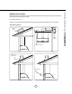
Installation – Mounting Height & Clearance www.zephyronline.com Minimum mount height between range top and KRRG ERWWRP VKRXOG EH QR OHVV WKDQ ´ Maximum mount height should be no higher than ´ It is important to install the hood at the proper mounting height.
NEVER exhaust air or terminate duct work into spaces between walls, crawl spaces, ceiling, attics or garages. All exhaust must be ducted to the outside. Use metal ductwork only.
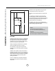
2-3/4” 4-3/16” 1-1/8” 2” 1-1/4” 29-61/64” - (30“), 35-61/64” - (36“), 47-29/32” - (48”) 9-29/32” 27-7/8” - (30“), 33-7/8” - (36“), 45-53/64 - (48”) 2-3/4” 3-19/32” 2” 12” 2” 5-5/32” 4-3/16” 5-5/32” R2 0” 22-1/8” ext. blower knock-out AC power knock-out 8 10-23/64” 57- 7/8” 7/ 8” or 11-31/32” 8-5/8” Installation – +RRG 6SHFL¿FDWLRQV www.zephyronline.
WARNING $OO (OHFWULFDO ZRUN PXVW E\ SHUIRUPHG E\ TXDOL¿HG HOHFWULFLDQ RU SHUVRQ ZLWK VLPLODU WHFKQLFDO NQRZ how and background. For personal safety, remove house fuse or open circuit breaker before beginning installation. Do not use extension cord or adapter plug with this appliance. Follow national electrical codes or prevailing local codes and ordinances.
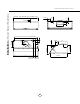
Installation – Internal Blower (Vertical Ducting) www.zephyronline.com INTERNAL BLOWER PREPARATION – VERTICAL DUCTING 1. Attach capacitor box to inside of hood using two M4*10 screws included with internal blower. 2. Attach green ground wire to ground screw on hood. 3. Connect 6 pin male connector from capacitor box to 6 pin female connector on control board box. 3ODFH ´ URXQG PRXQWLQJ SODWH RQ WRS RI KRRG and secure using eight M4*8 screws. 5. Install internal blower into hood. 6.
Installation – Internal Blower (Vertical Ducting) 7. Connect 9 pin male connector from blower to 9 pin female connector on capacitor box.
Installation – Internal Blower (Horizontal Ducting) www.zephyronline.com INTERNAL BLOWER PREPARATION – HORIZONTAL DUCTING 1. Attach capacitor box to inside of hood using two M4*10 screws included with internal blower. 2. Attach green ground wire to ground screw on hood. 3. Connect 6 pin male connector from capacitor box to 6 pin female connector on control board box. 4. Place solid mounting plate on top of hood and secure using eight M4*8 screws. 5. Remove rectangular cap from back of hood.
8. Install blower with round to rectangular adapter into hood. 9. Mount blower brackets to hood using two ´ ´ VFUHZV IRU HDFK EUDFNHW 6FUHZV are included with internal blower. 10. Install rectangular starting collar to back of hood using six M4*8 screws recently removed from rectangular cap (three screws on each side). Install four additional M4*8 screws in the top and bottom middle of rectangular starting FROODU &KHFN DQG YHULI\ LQQHU DGDSWHU LV ¿UPO\ secured. 11.
Installation – External Blower Preparation www.zephyronline.com EXTERNAL BLOWER PREPARATION 3ODFH ´ URXQG PRXQWLQJ SODWH RQ WRS RI KRRG and secure using eight M4*8 screws. 2. Install threaded cable lock and external blower wiring through the knockout next to the electrical wiring knockout. 3. Place cap over threaded cable lock and secure by turning cap clockwise. NOTE: Due to the size of the cap, it may be easier to install it after the hood has been mounted. 4.
%HJLQ LQVWDOODWLRQ E\ UHPRYLQJ WKH EDIÀH ¿OWHUV 5. Duct opening cutout 5HLQIRUFH FDELQHW ZLWK ´ [ ´ ZRRG VWULSV LI additional strengthening is required. Must be placed inside frameless cabinets. 4. Temporarily position the range hood in the desired mounting location. Measure and mark the mounting holes, duct and electrical locations with a pencil. NOTE: ,I XVLQJ DQ LQWHUQDO EORZHU D ´ URXQG duct opening is necessary.
Features & Controls – Touch Controls www.zephyronline.com 4 Lights On/Off/Dim 3 5 Min Delay Off 5 Display (Speed level, Delay Off Indicator) 1 Blower On/Off 2 Adjust 3 Speed Levels 1 Blower On/Off By pressing , the blower is switched On and Off. When switched on, the blower starts up on the same speed it was turned off at. When switched off the entire hood powers off, including the lights. 2 Speed Selection The 3 speed levels are selected by pressing to decrease and to increase speed level.
Clean periodically with hot soapy water and clean cotton cloth. Do not use corrosive or abrasive detergent, or steel wool/scoring pads which will scratch and damage surface. For heavier soil use liquid degreaser.
Maintenance – Lights www.zephyronline.com REPLACING LIGHT BULBS CAUTION: Light bulb becomes extremely hot when turned on. DO NOT touch bulb until switched off and cooled. Touching hot bulbs could cause serious burns. Make sure all power is turned off and bulbs are not hot. Remove by turning bulb counter clockwise. ,I EXOEV DUH GLI¿FXOW WR WXUQ GXH WR SURORQJHG XVH ¿UPO\ DWWDFK D JODVV VXFWLRQ FXS DSSUR[LPDWHO\ the diameter of the bulb and turn.
Issue Cause What to do After installation, the unit doesn’t work. 1. The power source is not turned ON. 1. Make sure the circuit breaker and the unit’s power is ON. 2. The power line and the cable locking connector is not connecting properly. 2. Check the power connection with the unit is connected properly. 3. The switch board and control board wirings are disconnected. 3. Make sure the wirings between the switch board and control board are connected properly. 4.
Warranty www.zephyronline.com TO OBTAIN SERVICE UNDER WARRANTY: or any Service Related Questions, please call: 1-888-880-8368 Staple your receipt here. Proof of the original purchase date is needed to obtain service under the warranty. TO OBTAIN SERVICE UNDER WARRANTY: You must present proof of original purchase date. Please keep a copy of your dated proof of purchase (sales slip) in order to obtain service under warranty.