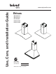
brisaS Use, Care, and Installation Guide by Brisas BMI-E36AG BMI-E36AS BSI-E36AS BVE-E30AS BVE-E36AS Model number: Serial Number: SEP08.0101 © Zephyr Corporation www.zephyronline.
www.zephyronline.
INSTALLATION Ducting Calculation Sheet ....................................... Mounting Height & Clearance................................ Ducting Options ........................................................... Hood Speci cations ................................................... Mounting the Hood BMI & BSI .............................. Mounting the Hood BVE................................. Ductless Recirculating ..............................................
www.zephyronline.com Important Safety Notice READ AND SAVE THESE INSTRUCTIONS WARNING TO REDUCE THE RISK OF FIRE OR ELECTRIC SHOCK, DO NOT USE THIS FAN WITH ANY SOLID-STATE CONTROL DEVICE. WARNING TO REDUCE THE RISK OF FIRE ELECTRIC SHOCK, OR INJURY TO PERSONS, OBSERVE THE FOLLOWING: a. Use this unit only in the manner intended by the manufacturer, if you have questions, contact the manufacturer. b.
TO REDUCE THE RISK OF FIRE, USE ONLY METAL DUCTWORK. CAUTION To reduce risk of fire and to properly exhaust air outside - Do not vent exhaust air into spaces within walls, ceilings, attics, crawl spaces or garages. OPERATION Always leave safety grilles and filters in place. Without these components, operating blowers could catch onto hair, fingers and loose clothing.
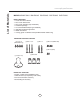
List of Materials www.zephyronline.com MODELS: BMI-E30AS BMI-E30AG BSI-E30AG BVE-E30AS BVE-E36AS PARTS SUPPLIED 1 - Hood with internal blower 1 - Duct cover wall bracket 1 - Duct cover assembly (top and bottom) 1 - Hardware package 1 - 6” round backdraft damper (pre-installed) 2 - 50W GU-10 halogen light bulbs 2 - Metal mesh filters 1 - Canopy, glass or stainless steel (for BMI and BSI models only) HARDWARE PACKAGE CONTENTS (4) 3/16” x 8 (BMI & BSI Only) (3) M4 x 1-1/2” (2) M4 x 1” (4) M3.
Equivalent number length x used = Duct pieces Total Total 3-1/ 4” x 10” 1 Ft. Rect., straight x( ) = Ft. 6”- 8” Round 30 Ft. wall cap with damper x( ) = Ft. 7” Round, straight 1 Ft. x( ) = Ft. 6”- 8” Round, 30 Ft. roof cap x( ) = Ft. 8” Round, straight 1 Ft. x( ) = Ft. 6” round to 1 Ft. 3-1/ 4” x 10” rect. transition x( ) = Ft. 3-1/ 4” x 10” 15 Ft. Rect. 90 0 elbow x( ) = Ft. x( ) = Ft. 3-1/ 4” x 10” 9 Ft. Rect. 45 0 elbow x( ) = Ft. 6” round to 16 Ft.
Installation – Mounting Height & Clearance www.zephyronline.com Minimum mount height between range top to hood bottom should be no less than 24”. Maximum mount height should be no higher than 32”. * Min. ducted (A) Min. recirc. (B) Max. (C) It is important to install the hood at the proper mounting height. Hoods mounted too low could result in heat damage and fire hazard; while hoods mounted too high will be hard to reach and will loose its performance and efficiency. Min 24” - Max.
NEVER exhaust air or terminate duct work into spaces between walls, crawl spaces, ceiling, attics or garages. All exhaust must be ducted to the outside, unless using the recirculating option. Use single wall rigid Metal ductwork only. Fasten all connections with sheet metal screws and tape all joints w/ certified Silver Tape or Duct Tape.
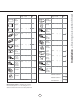
Installation – BMI Hood Specifications www.zephyronline.com 4 21 9 # 6 21 9 # Njo/!evdufe!34ϙ Njo/!Sfdjs/!37.
Installation – BSI Hood Speci¿cation 3 10 8 " 5 10 8 " Njo/!evdufe!34ϙ Njo/!sfdjs/!37ϙ Nby/!evdufe!51ϙ! 7 15 16 " 3 19 4 " 15 25 16 " 7 35 16 " 7 3 8 " 7ϙ 9
4 9 5 # 8 7 9 # 22 9 27 # 4 7 5 # Njy/!evdufe!38.203ϙ Njo/!sfdjs/!43ϙ Nby/!evdufe!53.203ϙ 52/4 23# ± Installation – BVE Hood Specification www.zephyronline.
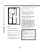
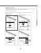
2. Plum and mark center line. 3. Mark mounting height line B. (15-3/8” from line A) 8-7/8” 4. Mark mounting spread from C/L. (8-7/8”) 5. Fasten (2) M4 x 1-1/2” screws into studs on line B but do not tighten all the way. Note: Wood blocking may need to be added behind the drywall if no studs are present. Wall anchors may also be used but check local codes before using wall anchors. 15-3/8” 6. Remove the (2) metal mesh filters. 7.
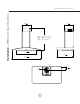
Installation – Mounting the Hood - BVE www.zephyronline.com ! CAUTION: At least two installers are required due to the weight and size of the hood. C/L 1. Measure from range top to hood bottom and mark line A. (24” minimum from range top) . Duct Cover Bracket 2. Plum and mark center line. 4" 3. Mark mounting height line B. (12” from line A) B 4. Mark mounting spread from C/L on line B. (4”) 12" 5. Fasten (2) M4x1-1/4” screws into studs on line B. Do not fasten screws all the way.
Installation – Ductless Recirculating Ductless recirculation is intended for applications where an exhaust duct work is not possible to be installed. When converted, the hood functions as a recirculating hood rather than an exhaust hood. Fumes and exhaust from cooking are drawn and filtered by a set of optional charcoal filters. The air is then purified and recirculated back within the home.
Features & Controls - Touch Controls www.zephyronline.
Clean periodically with hot soapy water and clean cotton cloth. Do not use corrosive or abrasive detergent , or steel wool/scouring pads which will scratch and damage surface. For heavier soil use liquid degreaser. After cleaning it is recommended that you use non-abrasive stainless steel polish/cleaners, to polish and buff out the stainless luster and grain. Always scrub lightly, with clean cotton cloth, and with the grain. Do not use any product containing chlorine bleach. Do not use “orange” cleaners.
Maintenance – Lights www.zephyronline.com REPLACING LIGHT BULBS CAUTION: Light bulb becomes extremely hot when turned on. DO NOT touch bulb until switched off and cooled. Touching hot bulbs could cause serious burns. Make sure all power is turned off and bulbs are not hot. Remove by turning bulb counter clockwise. Note: Bulb does not unscrew; it turns 60 degrees, stops and falls out.
Issue Cause What to do After installation, the unit doesn’t work. 1. The power source is not turned ON. 1. Make sure the circuit breaker and the unit’s power is ON. 2. The power line and the cable locking connector is not connecting properly. 2. Check the power connection with the unit is connected properly. 3. The switch board and control board wirings are disconnected. 3. Make sure the wirings between the switch board and control board are connected properly. 4.
List of Materials www.zephyronline.com DESCRIPTION PART# Replacement Parts Light Bulb GU-10 50W (each) Z0B-0020S Optional Accessories Recirculating Kit Replacement Charcoal Filter Duct Cover Extension BRC-0002 (for BMI & BSI) BRC-0001 (for BVE) Z0F-C002 B1C-00MI (for BMI & BSI) B1C-00VE (for BVE) To order parts, visit us online at http://store.zephyronline.com or call us at 1.888.880.
brisaS STAPLE YOUR RECEIPT HERE Proof of the original purchase date is needed to obtain service under warranty by Limited Warranty TO OBTAIN SERVICE UNDER WARRANTY OR FOR ANY SERVICE RELATED QUESTIONS, please call: 1-888-880-8368 Zephyr Corporation (referred to herein as “we” or “us”) warrants to the original consumer purchaser (referred to herein as “you” or “your”) of Zephyr products (the “Products”) that such Products will be free from defects in materials or workmanship as follows: One Year Limite