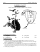
StairMaster ®Zephyr A SSEMBLY I NSTRUCTIONS / O WNERS M ANUAL IMPORTANT: SAFETY : Part No. 060-0036 READ ALL ASSEMBLY INSTRUCTIONS AND SAFETY PRECAUTIONS BEFORE USING THIS PRODUCT. REFERENCE ALL SAFETY GUIDELINES AND WARNING LABELS. RETAIN PRODUCT LITERATURE FOR FUTURE REFERENCE. PROPERLY WARM UP AND STRETCH BEFORE EXERCISING. IF YOU FEEL PAIN OR DIZZINESS AT ANY TIME WHILE EXERCISING , STOP IMMEDIATELY AND CONSULT YOUR PHYSICIAN.
PAGE 1 ASSEMBLY INTRO ASSEMBLY PREPARATION To ensure ease of product assembly, please take time to verify the size and quantities of all required assembly hardware. Use the itemized parts listing and hardware chart for reference. The product assembly process has been documented in easy to follow stages. Please read all assembly instructions carefully. Take time to review the manual and familiarize yourself with the entire assembly process before proceeding.
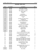
ASSEMBLY PARTS LISTING PAGE 2 ASSEMBLY PARTS LIST Item # Part Number Description QTY.
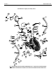
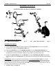
PAGE 3 EXPLODED VIEW StairMaster® Zephyr Assembly Parts 12 13 14 28 5 9 11 27 35 36 16 4 26 6 7 26 8 24 12 10 23 20 34 33 25 1 3 18 22 21 24 15 23 17 24 23 29 2 22 19 30 31 23 24 NOTE: NOTE: THE EXPLODED PARTS VIEW IS SHOWN FOR REFERENCE ONLY. SOME ITEMS MAY BE PREASSEMBLED. PLEASE REFER TO THE INDIVIDUAL ASSEMBLY STAGE INSTRUCTIONS FOR DETAILED PARTS ORIENTATION.
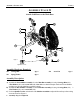
ASSEMBLY INSTRUCTION PAGE 4 ASSEMBLY STAGE #1 Attach Stabilizers to the Main Base 1 24 23 3 24 23 22 2 Figure 1 22 Adjustable Levelers Assembly Hardware Required: #22 Carriage Bolt Qty. 4 #23 Spring Washer Qty. 4 #24 Acorn Nut Qty. 4 Assembly Description: A) Assemble the Front Stabilizer Assembly (#2) to the Main Base Assembly (#1) using 2-Carriage Bolts (#22), 2-Flat Washers (#23), and 2-Acorn Nuts (#24).
PAGE 5 ASSEMBLY INSTRUCTION ASSEMBLY STAGE #2 Attach Console Mast & Mount Computer on the Main Base 5 4 26 6 Computer Back View 34 25 33 Figure 2 #4 Sensor Wire Assembly Hardware Required: #25 Carriage Bolt Qty. 2 #33 Spring Washer Qty. 2 #26 Pan Head Screw Qty. 2 #34 Acorn Nut M6 Qty. 2 Assembly Description: A) Carefully route the Sensor Cable (#4) through the Computer Mast (#6) and slide the mast down onto the corresponding mounting area of the Base Frame Assembly.
PAGE 6 ASSEMBLY INSTRUCTION ASSEMBLY STAGE #3 Attach Seat Slider and Seat to Main Base Assembly 12 14 28 13 9 11 27 7 8 12 10 Assembly Hardware Required: #27 Button Head Allen Bolt Qty. 2 #28 Button Head Allen Bolt Qty. 2 Assembly Description: A) Insert the Adjustable Seat Slider (#7) into the u-channel of the Seat Support Post (#8). Secure the seat slider assembly in place using the 1-Seat Adjustment Knob (#10).
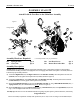
ASSEMBLY INSTRUCTION PAGE 7 ASSEMBLY STAGE #4 Attach Pivot Arms to the Main Base 16 Pivot-Boss Fan Safety Knob Figure 3 24 Pivot Shaft 23 31 30 17 23 Figure 4 24 30 Place #31 Flat Washer in-between the Connecting Arm and the Pivot Arm Assembly Hardware Required: #23 Spring Washer Qty. 2 #30 Pivot Bolt M8 Qty. 2 #24 Acorn Nut M8 Qty. 2 #31 Flat Washer Qty.
P AGE 8 ASSEMBLY INSTRUCTION ASSEMBLY STAGE #5 Attach Pedals & Foot Rest to the Main Base Assembly Figure 5 36 ® Right Pedal 35 20 18 26 24 23 21 29 19 Figure 6 Assembly Hardware Required: (*Assembly hardware may be preinstalled) #23 Spring Washer Qty. 6 #26 Pan Head Screw* Qty. 2 #24 Acorn Nut Qty. 6 #29 Button Head Allen Bolt Qty. 6 Assembly Description: Assembly Note: The right and left pedals are appropriately marked (R) and (L).
COMPUTER OPERATION PAGE 9 BUTTON FUNCTIONS MODE THE “MODE” BUTTON WILL SELECT AND SCROLL THROUGH EACH DISPLAY FUNCTION. RESET THE RESET BUTTON CAN BE USED TO ZERO OUT AN INDIVIDUAL DISPLAY FUNCTION. TOTAL RESET THIS BUTTON WILL ZERO OUT ALL DISPLAY READINGS AND PRESET VALUES. NOTE: THE REMOVAL OF THE BATTERIES WILL ALSO RESET ALL DISPLAY FUNCTIONS TO ZERO. UP THIS BUTTON ADJUST (INCREASES) FUNCTION VALUES. DOWN THIS BUTTON ADJUST (DECREASES) FUNCTION VALUES .
COMPUTER OPERATION PAGE 10 DISPLAY FUNCTIONS (Continued) CALORIE COMPUTER ACCUMULATES TOTAL CALORIE CONSUMPTION (BURN) DURING A TRAINING PERIOD. COMPUTER WILL COUNT IN 1 CALORIE INCREMENTS, FROM 0 TO A MAXIMUM READING OF 9999 CALORIES. PRESET A TARGET CALORIE BURN: USE THE MODE” BUTTON TO SCROLL TO THE CALORIE FUNCTION AND PRESS THE “UP OR DOWN” BUTTONS. SETTINGS CAN BE ENTERED IN INCREMENTS OF 10 CALORIES AND THE COMPUTER WILL COUNT DOWN FROM THE SET CALORIE VALUE.
PAGE 11 TROUBLESHOOTING BASIC TROUBLESHOOTING TIPS PROBLEM DESCRIPTION NO DISPLAY SUGGESTED SOLUTION 1) CHECK BATTERY ORIENTATION: + / 2) CHECK BATTERY VOLTAGE: (2) AA BATTERIES 1.5 VOLTS EACH CHECK CABLE CONNECTIONS: MAKE SURE CONNECTIONS ARE 3) SECURE AND IN THE CORRECT ORIENTATION. CHECK CABLE ASSEMBLIES FOR DAMAGE: PINCH POINTS & 4) POSSIBLE SHORTING OF WIRES. CHECK FOR POSSIBLE COMPUTER DAMAGE: CRACKED DISPLAY 5) WINDOW (BLACK SCREEN).
PREVENTATIVE MAINTENANCE PAGE 12 EQUIPMENT MAINTENANCE Use a dampened soft-cloth to wipe equipment free of perspiration after each use. Avoid getting excessive moisture on computer or electronic components. Do not use abrasive cleaners or petroleum-based solvents to clean equipment. Do not remove drive train shrouds or attempt any technical service on equipment without consulting an authorized service representative. Regularly inspect product for lose assembly hardware and worn components.
General Terms & Conditions AGE 13 P All StairMaster® exercise products are warranted to be free from defects in materials and workmanship under the terms of recommended use and warranty coverage.
P AGE 14 PRODUCT REGISTRATION Thank you for purchasing a StairMaster® product. Our products are designed and manufactured to the highest quality standards. We are committed to our customers satisfaction and we will do everything we can under the conditions of your product warranty to keep you secure in your product purchase. To help us serve you better, please fill out this Product Registration form & return it to us within 30-days of product purchase.
StairMaster 8000 NE Parkway Drive, Suite 220 Vancouver, WA 98662 1-888-678-2476 www. stairmaster.